Spatial Localization of 3D Scanned EEG Electrodes with MeshLab
Joel P Diaz-Fong, Jordana Glouberman, Agatha Lenartowicz
Disclaimer
DISCLAIMER – FOR INFORMATIONAL PURPOSES ONLY; USE AT YOUR OWN RISK
The protocol content here is for informational purposes only and does not constitute legal, medical, clinical, or safety advice, or otherwise; content added to protocols.io is not peer reviewed and may not have undergone a formal approval of any kind. Information presented in this protocol should not substitute for independent professional judgment, advice, diagnosis, or treatment. Any action you take or refrain from taking using or relying upon the information presented here is strictly at your own risk. You agree that neither the Company nor any of the authors, contributors, administrators, or anyone else associated with protocols.io, can be held responsible for your use of the information contained in or linked to this protocol or any of our Sites/Apps and Services.
Abstract
This protocol outlines step-by-step instructions for utilizing Meshlab's PickPoints tool to facilitate spatial localization of electroencephalogram (EEG) electrodes from 3D scanned head models. These include mesh models created from structured-light/infrared, photogrammetry, and LiDAR scanners, to name a few.
Before start
Download the latest version of the MeshLab software using the installer found on their website (www.meshlab.net) or download their source code directly from GitHub (https://github.com/cnr-isti-vclab/meshlab). For 3D scanning sample data, please visit: https://osf.io/87av2/
Steps
3D Scanning Setup
Participant Preparation
There are a few necessary steps to ensure that the participant is prepared in a way that guarantees a good quality scan. This includes:
Fiducial Visibility
- Identify Key Fiducials. Determine the anatomical landmarks (fiducials) to be used for coordinate registration (e.g., bridge of the nose, ears).
- Ensure Unobstructed View. Instruct participants to remove any accessories or items that may obstruct the visibility of fiducials during the scan. Also, verify that the bridge of the nose and ears are clearly visible in the final 3D mesh model.
Electrode Visibility
- Check Electrode Placement. Verify the correct placement of electrodes on the participant's scalp according to the EEG system used. Ensure that no electrodes are obstructed by hair or any other objects.
- Tuck Away Hair. Advise participants to ensure all strands of hair are neatly tucked away from the scanner's field of view of the electrodes.
Reduce Reflective Surfaces
- Identify Reflective Surfaces. Identify any reflective surfaces in the scanning environment that may impact electrodes visibility.
- Apply Non-Reflective Coverings. Use non-reflective stickers or a wax marker to cover reflective surfaces, especially those in close proximity to the electrodes.
Import Mesh Model
Import the Mesh Model
After acquiring a 3D mesh model, open the MeshLab software and import the 3D mesh file.
Software
| Value | Label |
|---|---|
| MeshLab | NAME |
| https://github.com/cnr-isti-vclab/meshlab | REPOSITORY |
| Visual Computing Lab - ISTI - CNR | DEVELOPER |
| https://www.meshlab.net/ | LINK |
| 2022.02 | VERSION |
Import mesh
- To do so, select File > Import Mesh…
Optional: Optional : Once the file is imported into the software, remove the trackball to get a better view of the mesh model.
- Select View > Show Trackball
- Unselect Show Trackball to remove the trackball

Spatial Localization
Open the PickPoints Tool PickPoints Tool
- Once the model is imported into the MeshLab software, you can begin to localize the fiducial and electrode coordinates with the PickPoints tool.
- To start, find the PickPoints icon in the toolbar or select Edit > PickPoints

PickPoints Icon
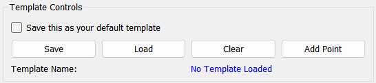
Enter Point Names or load an existing template
- Before you start selecting points on the mesh, manually enter each electrode label as a Point Name (see 5.2 about saving templates).
- If you have an existing template, go to Template Controls , select Load and choose the .pptpl template file.

Begin selecting points on the mesh
- Locate the fiducial or electrode on the mesh model and right-click the location with your cursor. A green pin should appear at that location.
- To rotate the mesh model, unselect PickPoints and rotate/drag the model with your curser. Once you've adjusted the model to the desired position, reselect PickPoints to continue.
.")

Selecting the fiducials
- As mentioned in 1.1, the fiducials (anatomical landmarks) should be determined beforehand. The fiducials should also be the same across all your scans for a given study.
- For the example in this protocol, we select the nasion (NAS), the left helix-tragus junction (LHJ), and the right helix-tragus junction (RHJ).
Selecting the electrodes
- Select each of the electrodes, point by point, following the order of the Point Names column.
- For a good approximation of the electrode location, try to select the point at the center of the electrode. The green pin should appear perpendicular to the scalp if the surface of the electrode is flat.
Save PickedPoints
Save electrode coordinates
- Select Save at the upper right-hand corner of the PickPoints tool.
Optional: Optional : save a snapshot
- Snapshots of the mesh model with the green coordinate pins can be saved as an image file, which is useful for documenting the quality of mesh model and how the fiducials were defined for the selected coordinate points.
- Go to File > Save snapshot
 can be removed for anonymity.")
Example snapshot of the mesh model with all the selected points. The model texture (or surface detail) can be removed for anonymity.
Optional: Optional : save the template of Point Names so the electrode labels can be loaded for processing multiple participants
- Under Template Controls , select Save . Templates are saved as a .pptpl filetype.
Extract Coordinates
Finally, the coordinates should be extracted from the PickedPoints file and converted to a preferred format.
Convert PickedPoints XML file to text
Extract coordinates from XML file and convert them to text.
Convert coordinates to a standard space
The coordinates that are extracted from the PickedPoints file are typically the same unit of measurement and coordinate space as the mesh model. Use the fiducials as a reference point to convert the coordinate space to a standard format.
