Inducing different severities of traumatic brain injury inDrosophilausing a piezoelectric actuator
Janani Saikumar, Joshua Kim, China N. Byrns, Matthew Hemphill, David F. Meaney, Nancy M. Bonini


Supplementary information
Supplementary Information
Supplementary Videos 1–4 legends, Supplementary Software 1 legend, Supplementary Figs. 1–6 and legends.
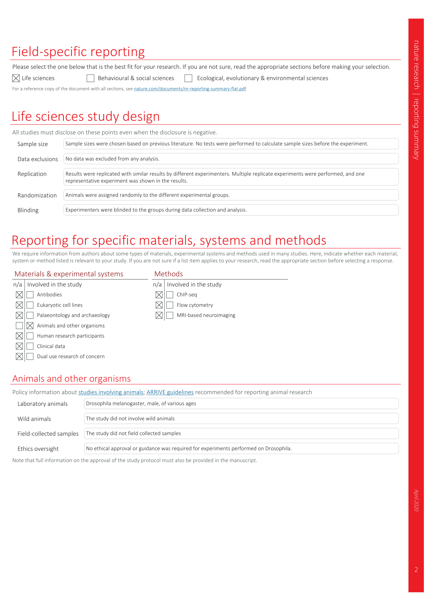
Reporting Summary
Supplementary Video 1
Severe compression in the low-throughput and high-throughput devices.
Supplementary Video 2
Calibration and compression measurements in the low-throughput device: The measurements of % head compression, the gap between the collar surface and piezoelectric actuator (purple), height of uncompressed fly head (green), height of fly head at the point of maximum compression (blue), and the gap between the head and the piezoelectric actuator (red) corresponding in location to the schematic in Fig 5b .
Supplementary Video 3
Collar loading and unloading protocol: A step-by-step guide on using a pair of blunt forceps to load the fly into the collar and move it along the groove with the forceps or a paintbrush.
Supplementary Video 4
dTBI procedure: A step-by-step guide on positioning the collar under the piezoelectric actuator and performing the injury.
Supplementary Software 1
Arduino code to operate dTBI device.
