3D Mesh Cleanup Tutorial: Fossil Plant Cupule (Beginner)
Elizabeth G. Clark, Kelsey M Jenkins, Craig R Brodersen
Abstract
This protocol details 3D mesh cleanup tutorial of fossil plant cupule (Beginner).
Attachments
Steps
Part 1: The Meshlab Interface
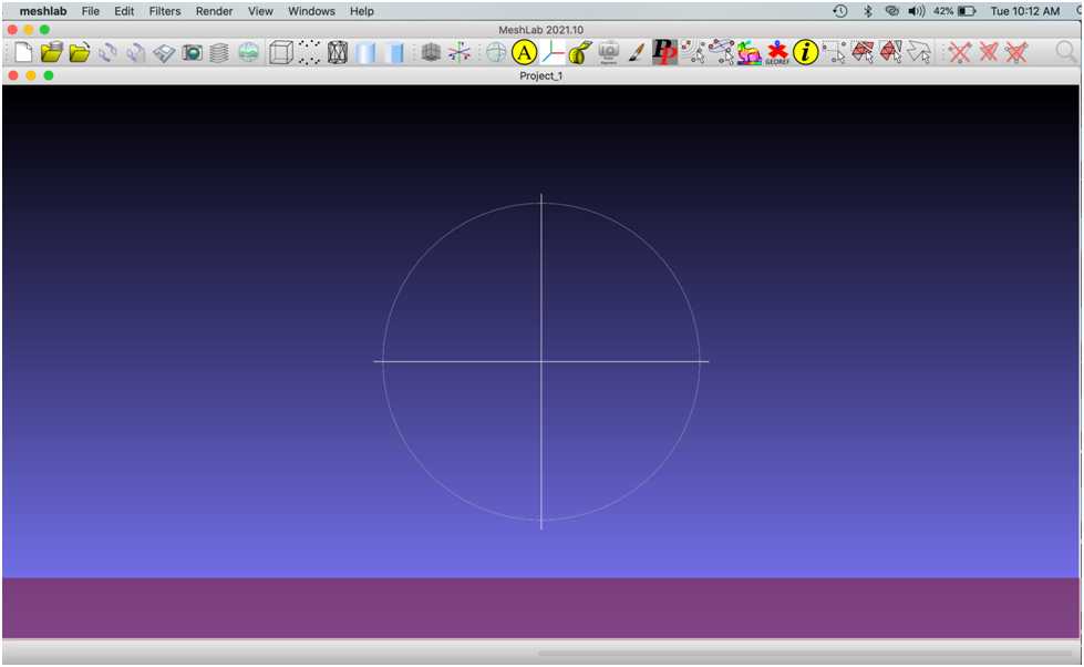
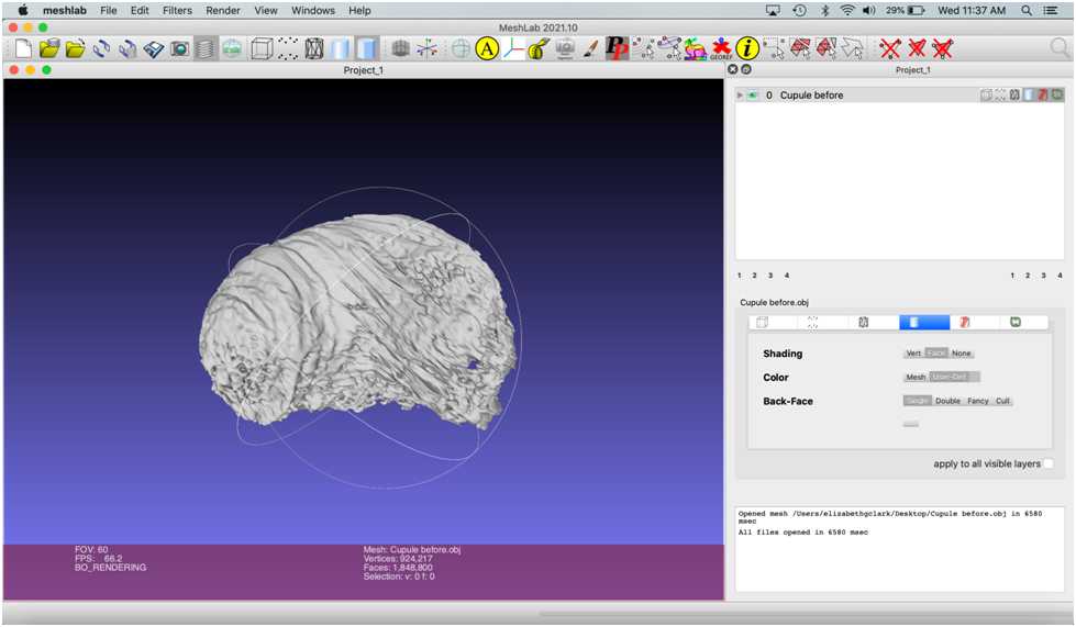
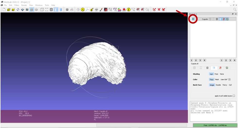
Open Meshlab and import “Cupule before.obj” into Meshlab via File > Import Mesh . Alternatively, drag the file into the project window (the large purple box with the crosshairs) if using Mac.
Keep the “unify duplicate vertices” box checked .
The mesh now appears in the project window. You can rotate it by holding left click and dragging the cursor.
Try repositioning the mesh .
Turn the visibility of the object on and off by clicking on the eye icon in the top right menu .
Zoom in by scrolling with the wheel of a mouse, swiping with two fingers (on a Mac trackpad), or holding down shift and left click (in both Mac and PC) while moving the cursor up and down.
Part 2: Shrinkwrapping the Mesh
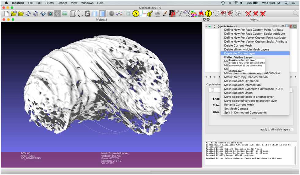
Create a new, simplified mesh over the surface of the cupule. This is known as “shrinkwrapping.” Shrinkwrapping the mesh smooths the surface and patches holes. Performed by isolating the vertices that make up the external structure of the cupule and using them to make a new mesh layer.
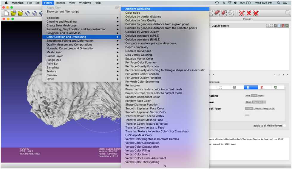
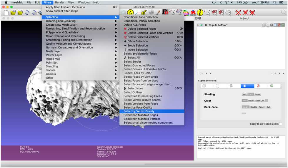
The first step is to hollow out – or remove the faces and vertices - from the inside of the mesh. The program will label which faces and vertices are inside the cupule and which are on the surface by clicking Filters > Color Creation and Processing > Ambient Occlusion .
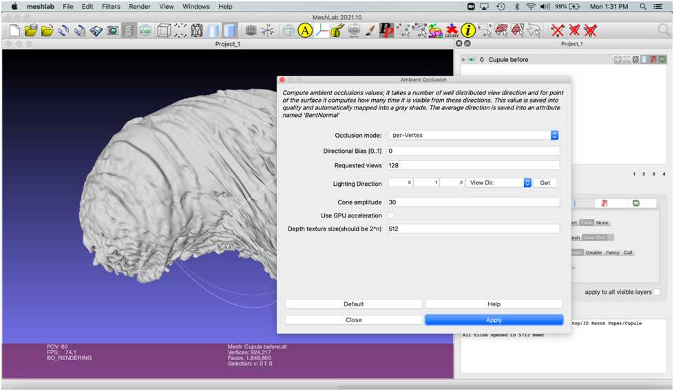
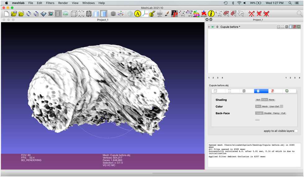
Click Apply on the pop-up menu. All other settings can remain as default.
Next, select the dark mesh components by clicking Filters > Selection > Select by Vertex Quality .
This selects mesh components with greyscale values within a set window. Select the darkest values, since these are the components located on the inside of the mesh.
To do this, set the “Min Quality” value to 0 .
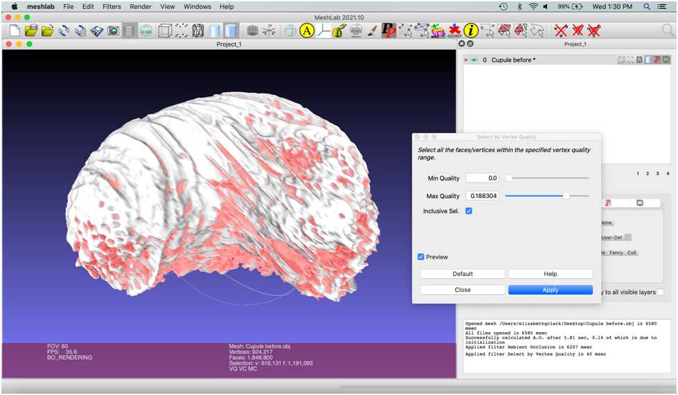
Next, check the “Preview” box , and a preview of the selected mesh components within that greyscale window will be highlighted in red.
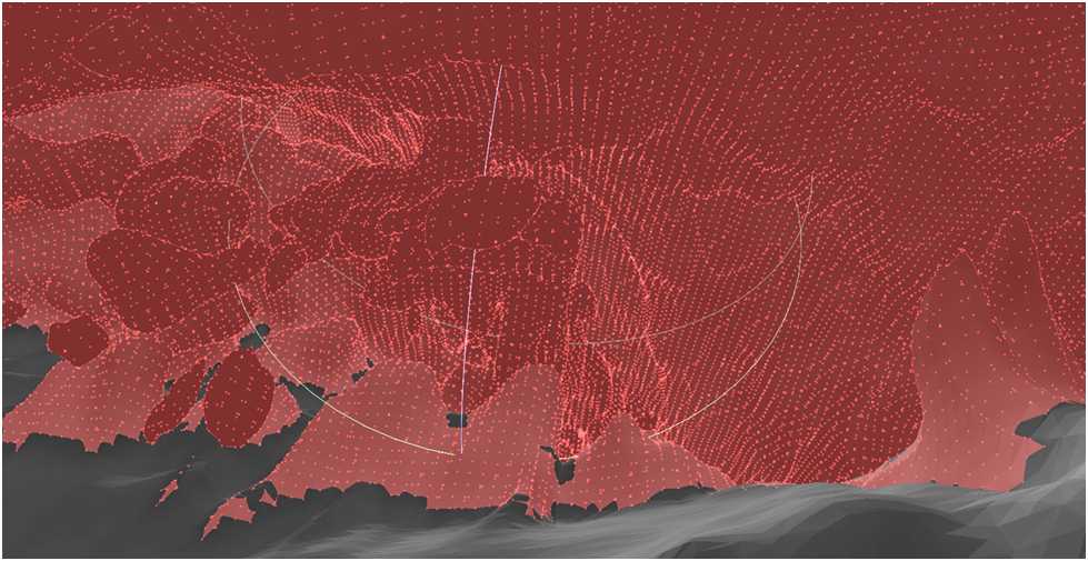
Zoom in and explore the view of the previewed selection inside the object.
Toggle the “Max Quality” slider until most of the inside components are selected.
Then, zoom out to view the external surface of the object. The goal is to set Max Quality to select the lowest number of faces on the outside while selecting the highest number on the inside: Max Quality was set to 0.188304 in this example. Once you have achieved this balance, hit “Apply.”
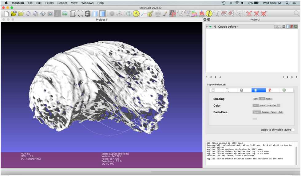
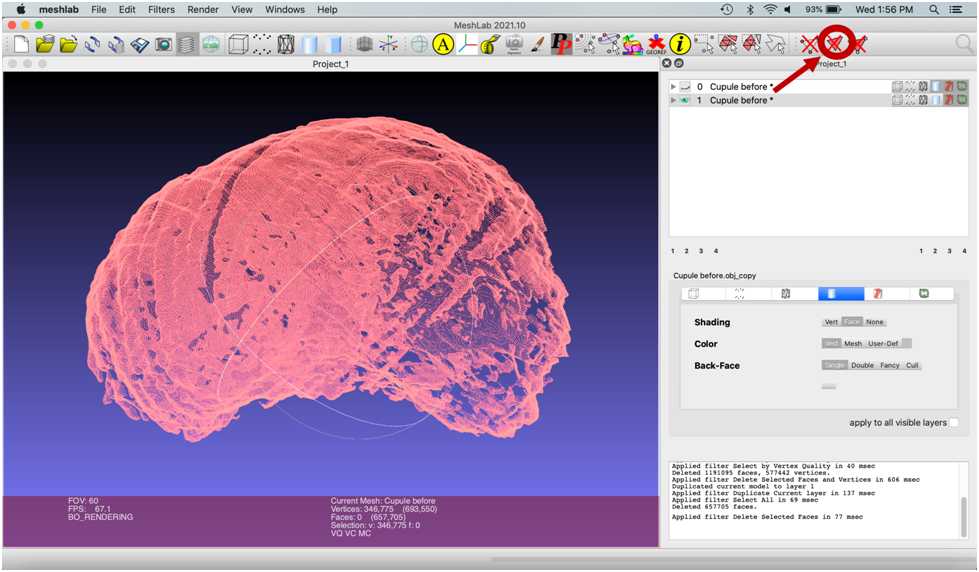
Select “Delete Selected Faces and Vertices” on the right of the icon-based menu towards the top of the screen. This will delete the faces and vertices in red selected in the previous step, leaving a shell of the original mesh.

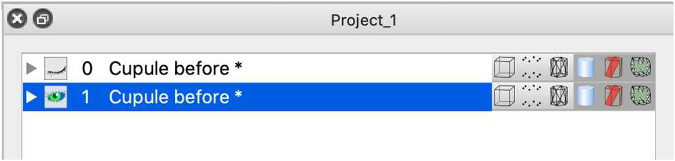
Click the eye in the top row to hide the original mesh. The eye will appear closed, indicating the layer is not visible. Click the second row to select the new mesh, since any commands performed will be done on the active selection.
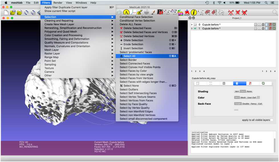
To remove all of the faces of the mesh , select Filters > Selection > Select All or press command + shift + A (Mac) or ctrl + shift + A (PC).
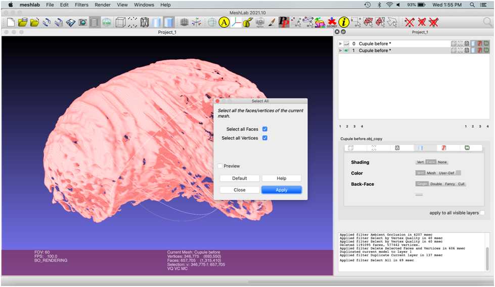
A pop-up menu will appear. Keep both boxed selected. Select “Apply”.
Delete all mesh faces by selecting “delete faces” icon in the icon-based menu :
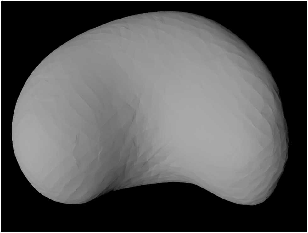
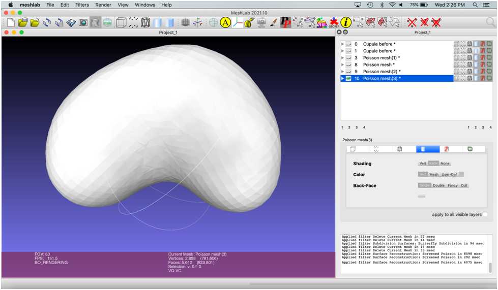
Next, the outer vertices of the cupule will be used to create a new mesh using a screened Poisson (Kazhdan and Hoppe, 2013).
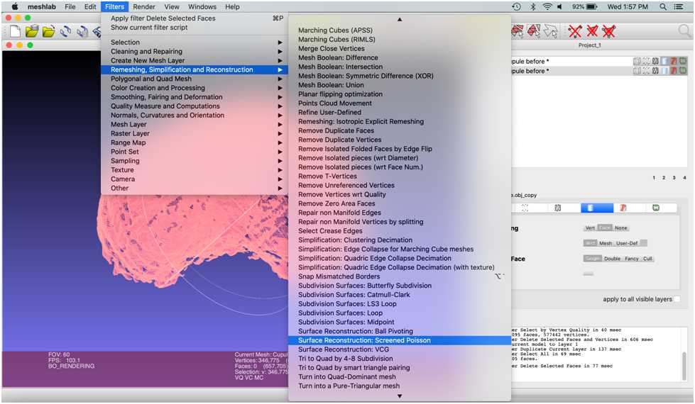
Go to Filters > Remeshing, Simplification and Reconstruction > Surface Reconstruction: Screened Poisson .
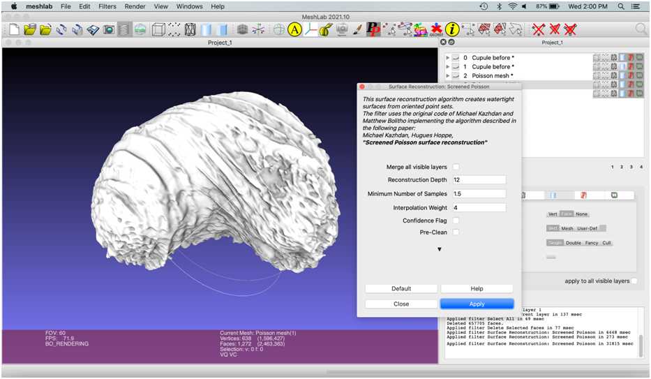
Check the “pre-clean” box , which removes any defects in the mesh that would keep the filter from working.
- Click “Apply” in the popup menu. A new layer named “Poisson mesh” will appear in the righthand menu.
- Click the eye of your previous mesh to view the poisson mesh by itself .

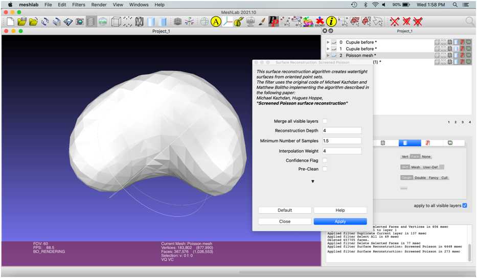
The “Reconstruction Depth” ranges from 1-12, with default value as 8. To see what different reconstruction depths look like, re-select the second layer in the object list, “Cupule before,” and run the filter again with a reconstruction depth value of 4 and 12 .
To rename a layer, Right click the layer > Rename Current mesh > rename the mesh > Apply.
Select the poisson mesh with the reconstruction depth of four and rename this mesh “Cupule remesh”.
Next, select Filters > Remeshing, Simplification and Reconstruction > Subdivision Surfaces: Butterfly Subdivision .
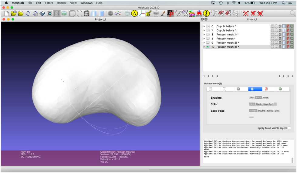
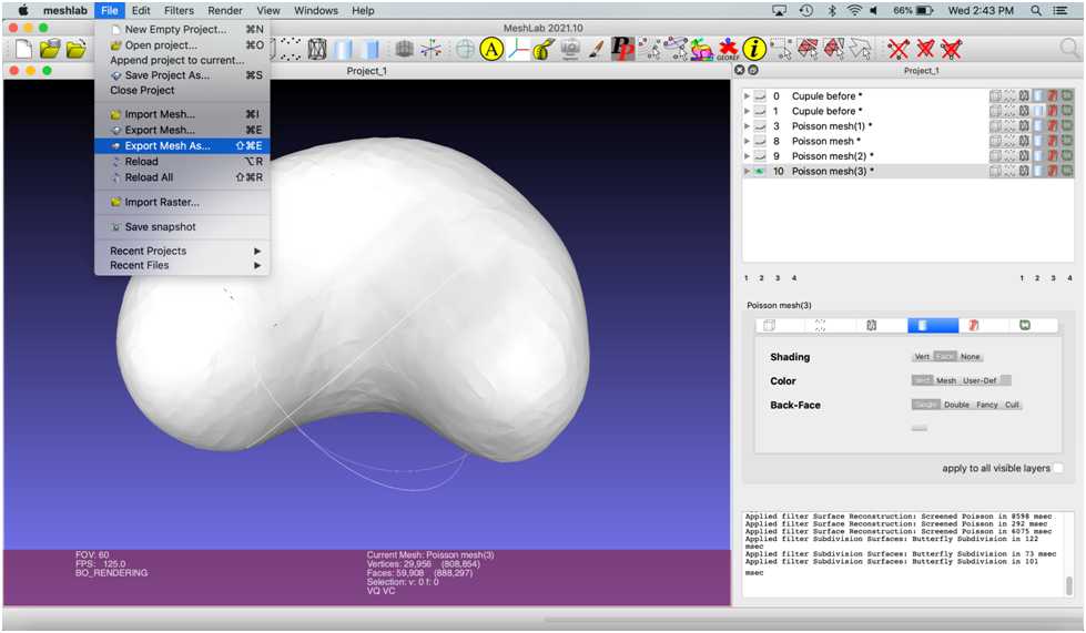
Once the reconstruction is complete, export the new mesh by selecting File > Export Mesh .
- Select .stl as the file type.