A Supplemental Guide to Building the optoPlate-96
Mary J Dunlop
Abstract
The optoPlate-96 is a device that uses small LEDs to illuminate cell cultures in a 96-well plate. It was developed by Lukasz Bugaj and Wendell Lim. If you haven’t read the original optoPlate-96 paper and its Supplementary Information you should start there (Bugaj and Lim, Nature Protocols 2019).
During the COVID-19 shutdown I made an optoPlate-96 in my basement over the course of many months. The protocol is detailed and awesome. But there are some things it doesn’t tell you, a few small typos, and several places where I just got confused. If you’ve never ordered a PCB or done reflow soldering, but are interested in giving it a try, this guide is for you.
Before start
Steps
Introduction
Here is what the final design looks like:
#尊敬的用户,由于网络监管政策的限制,部分内容暂时无法在本网站直接浏览。我们已经为您准备了相关原始数据和链接,感谢您的理解与支持。
<iframe src="https://drive.google.com/file/d/1TiCFbM52MbxBjh_146OLGgang9dKhDOc/preview" width="640" height="480" allow="autoplay"></iframe>
The Parts List
THE PARTS LIST
The first thing you’ll need to do after reading Bugaj and Lim, Nature Protocols 2019 in detail is actually order the parts you will need. Most of this is straightforward since they’re nicely listed in the Materials section, but there are a handful of things on the list that you don’t actually need and some places where you can get away with other approaches, so I’ll walk you through that in this section.
Ordering the PCB
You will need to get a quote for the printed circuit board (PCB) and the stencil. There are various places that will do this for you; I went with the PCB Unlimited option listed in the manuscript. Since it’s not the most standard order you’re actually going to have to talk to them on the phone and tell them what you need. This was challenging for me because I had no idea what I was buying, other than that I had a bunch of files I downloaded from GitHub. I ended up reading them the text in the paragraph about the stencils verbatim and then sending them the gerber and drill files (11 files in total) and that was enough for them to figure it out. They came back with quotes from 2 different manufacturers for the PCB. The two competing quotes were
PCB Unlimited dealt with placing the order with the company in China and they were shipped to me a few days later. The stencil was made by PCB Unlimited itself.
Note: These prices are as of fall 2020. I'm including them to give you a general sense of scale.
Electronic parts and accessories: What you actually need and what you don’t
There are many things on the Materials list that you need to buy, but there are also things that you only need if you screw up or want to do further optimization. I have organized these in a Google Sheet: Parts List.
I've highlighted any lines where I had comments about purchasing. There are also direct links to many of the products.
Another note: For many of the small, inexpensive components I would recommend rounding up on numbers a little. That way if you drop an LED on the floor and can't find it, it won't involve placing an entirely new order. This will also allow you to practice placing a few parts and doing the reflow soldering process on a practice PCB.
3D Printing
We have 3D printing facilities at Boston University so I submitted the designs there and it was straightforward. The only things you should be aware of here are that you need to print 4 copies of the heat sink pedestal. Also, the lid is fine but for the applications we use it for, which involve shaking it’s not great. We’re going to end up redesigning it.
The units for the *.stl files are mm.
Laser Cutting
I’m sure you could laser cut things, but we didn’t have facilities on campus and I didn’t have access to a machine shop because of COVID, so I found some workarounds.
-- Base Plate --
This is a piece of black plastic. I looked at the options for commercially laser cutting this and it was going to be quite pricey for a really, really simple design. I ended up cutting the rectangle to size using a circular saw and then using a cordless drill for the holes. I didn’t cut out the center hole for the fan because I wasn’t sure we needed it, but I’ll bet you could use a dremel to do this. Also, because we needed to attach it to our shaking incubator I had to drill additional custom holes so it really makes more sense to do this with a drill rather than going with some fancy laser cutting option, unless you’ve got easy access to laser cutting. If you don’t have a circular saw I’m sure other saw options would work. Also, acrylic smells terrible when you cut it and little plastic chips fly everywhere.
-- Thermal Pad --
You definitely don’t need to laser cut this. I used a drill for the holes, but you could probably poke a sharp pencil through and be fine. Also, the design on GitHub has a whole bunch of holes. You only need 4 of them. I'd recommend just waiting until you are at the point you need this and just cutting the holes where you need them then. This isn't hard.
-- Diffuser Film Squares --
I had some trouble sourcing this material and I wasn’t sure that we actually need it so I didn’t actually make these. If we end up deciding we do it then I think I’d just use a ruler and an exacto knife to make these.
Water Jet Cutting
There is a typo in the paper. The aluminum plate should be 1/16” and not 1/8”. This matters because the screws on the fan aren’t long enough to fit through a thicker aluminum sheet and all the hardware is sized for 1/16”.
You do actually need to make an aluminum plate and the tools I had in my basement won’t work for metal. Commercial solutions for this were crazy expensive and the design itself is simple. Your best bet here is to locate a machine shop on campus and either make it yourself or ask them to do it. I was trying to make this during the COVID shutdown and didn’t have this option in a contactless way. I’m sure no one else is in this position, but my dad (Al Dunlop) has a really extensive metal and wood working shop, so he offered to make it and mail it to me.
The design on GitHub has a ton of extra and unnecessary holes and some weird issues with units. In reality, the measurements just don’t need to be that exact, which is why it doesn’t matter. Here is a version of the design that just has the holes you actually need. (The original design is on the right.)
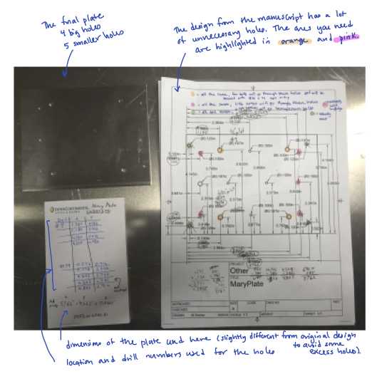
Here's a higher resolution version of this same picture: Plate.pdf
Supplemental Information for the Protocol
SUPPLEMENTAL INFORMATION FOR THE PROTOCOL
In this section I’m going to follow the numbering from the Protocol in the original paper. So when you see a number like (2) it refers to step 2 in Bugaj and Lim, Nature Protocols 2019.
Placement of components
(2) I found blue painters tape to work well for this because it's pretty secure, but easy to remove. I'm sure other options will work, too. I found it useful to only tape one side of the stencil (the side you'll scrape away from). This way you can lift up the stencil easily without having to remove tape.
(3) Before starting on the part where you deposit the solider paste you want to get your components ready to go. If you're just doing a test run with the solder paste and a few components then you don't have to get much ready, but when you're trying to build the whole thing I highly recommend a mise en place style approach. I made little bowls with labels and put the components in them.
The LEDs and various other things I got came in "tape and reel" packaging. I gather that I’m the only person in the world who got confused by how to open this since internet searching turned up nothing, but it turns out you can just peel the plastic film off the top of it and then dump the small parts into a bowl.
#尊敬的用户,由于网络监管政策的限制,部分内容暂时无法在本网站直接浏览。我们已经为您准备了相关原始数据和链接,感谢您的理解与支持。
<iframe src="https://drive.google.com/file/d/1TV860eMTTxljT2yHM39pOPszUhVO7g9u/preview" width="640" height="480" allow="autoplay"></iframe>
(3) What does "deposit solder paste liberally" mean? I found I had to put a lot on to get consistent coverage. The video below shows what I did. I'm putting the paste on in front of the spot that it's supposed to cover so that when it gets scraped across it spreads into the stencil hole.
#尊敬的用户,由于网络监管政策的限制,部分内容暂时无法在本网站直接浏览。我们已经为您准备了相关原始数据和链接,感谢您的理解与支持。
<iframe src="https://drive.google.com/file/d/1TWMO_57DLU3drxVVYroJletjzi0WK3T7/preview" width="640" height="480" allow="autoplay"></iframe>
(4) and (5) Here's a video of me doing these steps. I had to go back a few times and fix places where I could tell I didn't have good coverage with the solder paste. I tried not to do the vertical scrape step too many times, but as you'll see I had to go do a few rounds of it focusing on various spots. Off screen, I'm usually either removing solder excess solder paste from the spreader or adding a little more paste to it.
#尊敬的用户,由于网络监管政策的限制,部分内容暂时无法在本网站直接浏览。我们已经为您准备了相关原始数据和链接,感谢您的理解与支持。
<iframe src="https://drive.google.com/file/d/1TYimzOZJfpuwDMTSAuy98ceF4Y5XJe60/preview" width="640" height="480" allow="autoplay"></iframe>
(7) In my opinion, the LED driver chips are the hardest of all the components to place. I was never able to get them on without smearing the solder between the pads. What you are aiming for is to get the chip lined up with the pads nicely. Don't worry about it if the solder smears between the pads a bit as you gently nudge the chip into the right place with the tweezers. When you heat the solder it will kind of ball up on the metal pads and off of the plastic parts between them so I found that it actually fixed itself. Your goal should be to get the chip aligned with the pads well. Be patient here and just gently nudge the chip around.
(7) - (12) Here's a video of me doing these steps. One thing that I'd recommend is thinking about how to minimize moving your hands over the PCB while you're doing this to avoid accidentally knocking something out of place. Turning the board at various points will help you achieve this. (In case you miss it: I make a mistake in the video where I forget to place one of the LEDs, but fortunately I catch it.)
#尊敬的用户,由于网络监管政策的限制,部分内容暂时无法在本网站直接浏览。我们已经为您准备了相关原始数据和链接,感谢您的理解与支持。
<iframe src="https://drive.google.com/file/d/1TikuyX_pPaV3mRyZi_fV9QsxlEiZ_vr3/preview" width="640" height="480" allow="autoplay"></iframe>
(8) I think there may be a typo in Fig. S5b. The polarity may be swapped in the diagram, so you should confirm that you have the right orientation if you're using the blue LEDs. In general, you should look up the spec sheets for your LEDs and just double check the polarity.
(11) There's a potential typo in the paper, where the resistor values that are actually printed on the PCB board are different from what's shown in Fig. S11 in the 3-color configuration. I think there may be a typo on this Fig. S11 diagram for the far red resistor values (1.65 kΩ may be incorrect). This will be dependent on the LED colors you're actually working with, so just check this for your specific design.
Another small typo in the Fig. S11 diagram: there's an extra 10 kΩ resistor in the picture that doesn't actually exist on the board. It's the one that's in between the Arduino and the LED driver chips.
Reflow soldering
Before you do any reflow soldering you need to calibrate your toaster oven. To do this you need a thermometer, a toaster, and the general temperature profile you're looking to achieve. The temperature profile will come with the solder paste tube and will look something like this:
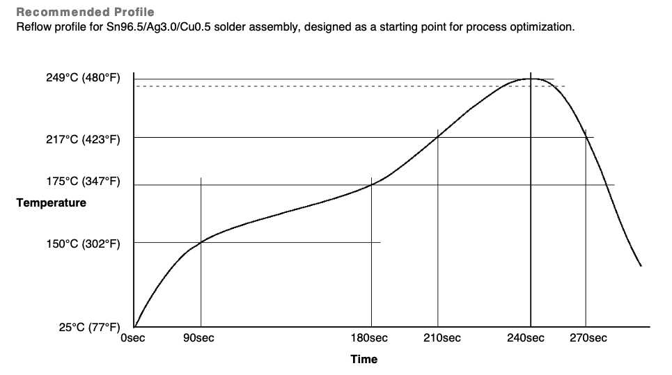
My recommendation is that you not use the inexpensive analog thermometer recommended in step (14), but instead use a rapid read digital oven thermometer of the sort you would use to measure the temperature of meat. You need it to be able to measure temperatures ranging from 25C - 250C, but most standard oven probe thermometers will do this. These aren't expensive items and the rapid and accurate readings will make calibration much easier.
Before I talk about calibration, a few notes about the toaster: I'm pretty positive you can use any toaster here. A low-end, inexpensive model should be fine. Do not use one that you ever intend to use for food again. Soldering generates some fumes and no one wants their toast to taste like solder (it's probably also not great for you).
Put the thermometer probe in the oven and measure how long and what toaster settings you need to achieve something like the temperature profile shown above. It'll take a little trial and error to figure this out and you don't have to be perfectly exact about it.
Here's what worked for my toaster:
- Start at room temperature
- Set toaster temperature to 200C, leave until temperature probe reaches 150C (takes 2.5-3 mins)
- Wait 20-30 sec
- Set toaster to 260C, leave until temperature probe reaches 217C and/or all the solder has melted (a total of 4-5 mins)
Here's an example of the notes I took while doing my toaster calibration: toaster_calibration.pdf. To be clear, you're doing this calibration all without a PCB in the toaster. After you get a solid protocol down you can do a practice run with a sacrificial PCB and a few components.
(15) - (18) I made a video of this whole process, which is below. You should expect to see some smoke and smell the solder, so do this in a ventilated area. The other thing I'll note is that just opening the toaster door and letting it cool without moving the board out is my recommendation. I tried to take my board out when it was still warm and managed to bump one of the components out of place. It was an easy one to fix, fortunately, but you should avoid this mistake by just letting it cool inside the open toaster. It won't take more than a few minutes.
#尊敬的用户,由于网络监管政策的限制,部分内容暂时无法在本网站直接浏览。我们已经为您准备了相关原始数据和链接,感谢您的理解与支持。
<iframe src="https://drive.google.com/file/d/1TgTtqa-JwA5rSjPoyOYs0BISJOzMTNwV/preview" width="640" height="480" allow="autoplay"></iframe>
Through-hole soldering
(20) I've done a little soldering before, but not a lot. I watched the Sparkfun tutorials and it wasn't too hard to do any of these soldering steps. The barrel jacks are the hardest (though not hard) because the holes you have to fill are pretty large so it takes more solder than the other components. If you haven't soldered much you will be fine, but practice with a few components on your spare board or something else first.
(24) I got confused by the instructions and did this backwards. The fan plugs in underneath the board. This header should be the opposite direction from the others you've put on the board. If you do this wrong, don't fret, you can just plug the fan in from the top.
Quality control
(25) It wasn't immediately obvious to me which way to insert the Arduino from the instructions. The place where the USB cable connects should be closest to the edge of the board. If you put it in backwards (which I definitely did...) it will light up, but it will do crazy thing like be very bright and blink.
Make sure you update the Arduino program to specify that it should be talking to the Arduino you're using here. This is only an issue if you've been using a different Arduino for some other project.
Also, the instructions about which library to download are in the Word file that's in this folder. It took me a little while to figure this out and I tried some other things first before finding this.
Full assembly of the optoPlate-96
(33) I used a popsicle stick to spread the thermal grease. A plastic knife of the sort you get with take out would also be good. You want something you can just toss after you're done.
(38) For our application, I didn't want screw heads sticking out the bottom of the acrylic since I wanted it to sit flush on the incubator platform so I used a slightly different design. There are some notes about what I did here: Base plate.pdf. But you'll probably just want to customize this for your application.
Other Information
OTHER INFORMATION
How long does it take to make?
The original protocol says you can make the optoPlate in 3-4 hours. This is true if you've made one before, have all the parts, and know what you are doing. It took me far longer to make my first one. From the time I first decided to make one until I had a finished version was about 4 or 5 months. I was doing this around all my other professor duties and at the time elementary schools were essentially closed so I was homeschooling my 5 and 7 year old girls. So consider that an upper bound on how long it will take. The videos you see here are ones I took when making a second optoPlate, so the process was much smoother. (It then took me another year to get around to writing this guide!)
Practicing steps
The original manuscript recommends sacrifice a PCB and a few components to practice the reflow process. I second this recommendation. It is inexpensive to order a few excess PCBs and components and it will allow you to practice placing parts, verify the reflow protocol using your toaster, and practice soldering.
Acknowledgements
Thank you to Lukasz Bugaj for letting me write up this supplemental guide on his work and also for publishing the protocol in the first place. Also, thank you to Al Dunlop his help with the aluminum plate and other advice on fabrication and construction. Finally, thank you to all members of the Dunlop Lab.
