Design and construction of a microfluidics workstation for high-throughput multi-wavelength fluorescence and transmittance activated droplet analysis and sorting
Christoph A. Merten, Jatin Panwar, Alexis Autour


Extended
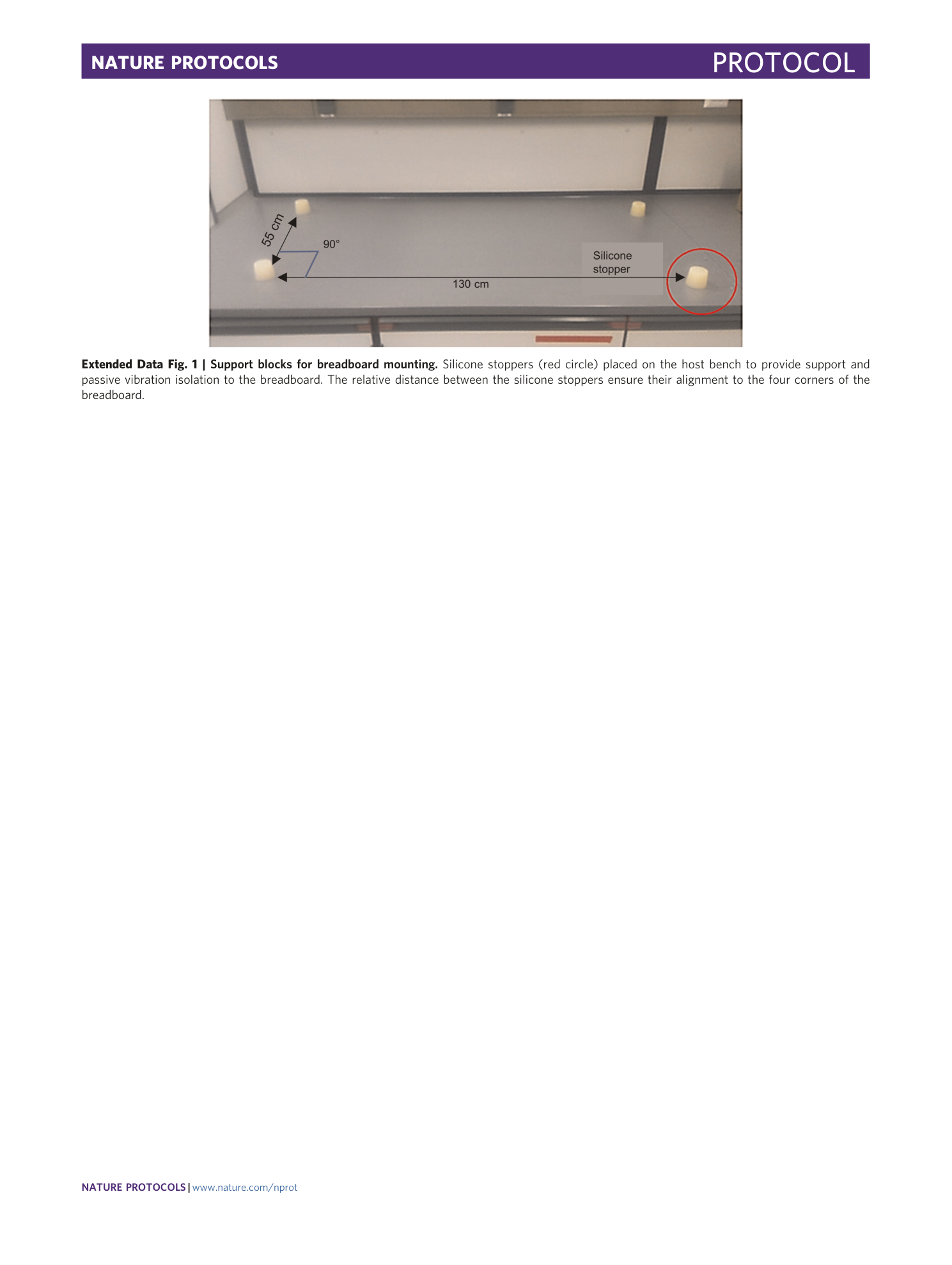
Extended Data Fig. 1 Support blocks for breadboard mounting.
Silicone stoppers (red circle) placed on the host bench to provide support and passive vibration isolation to the breadboard. The relative distance between the silicone stoppers ensure their alignment to the four corners of the breadboard.
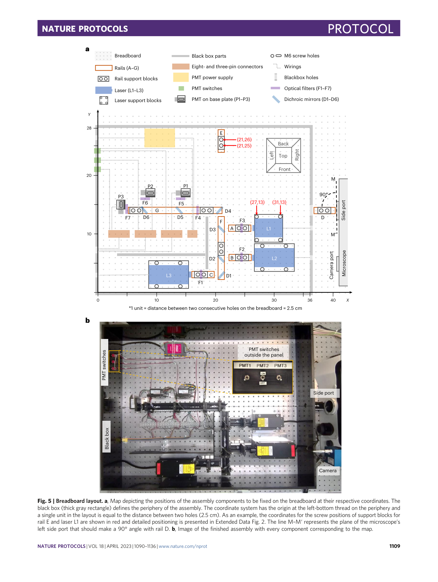
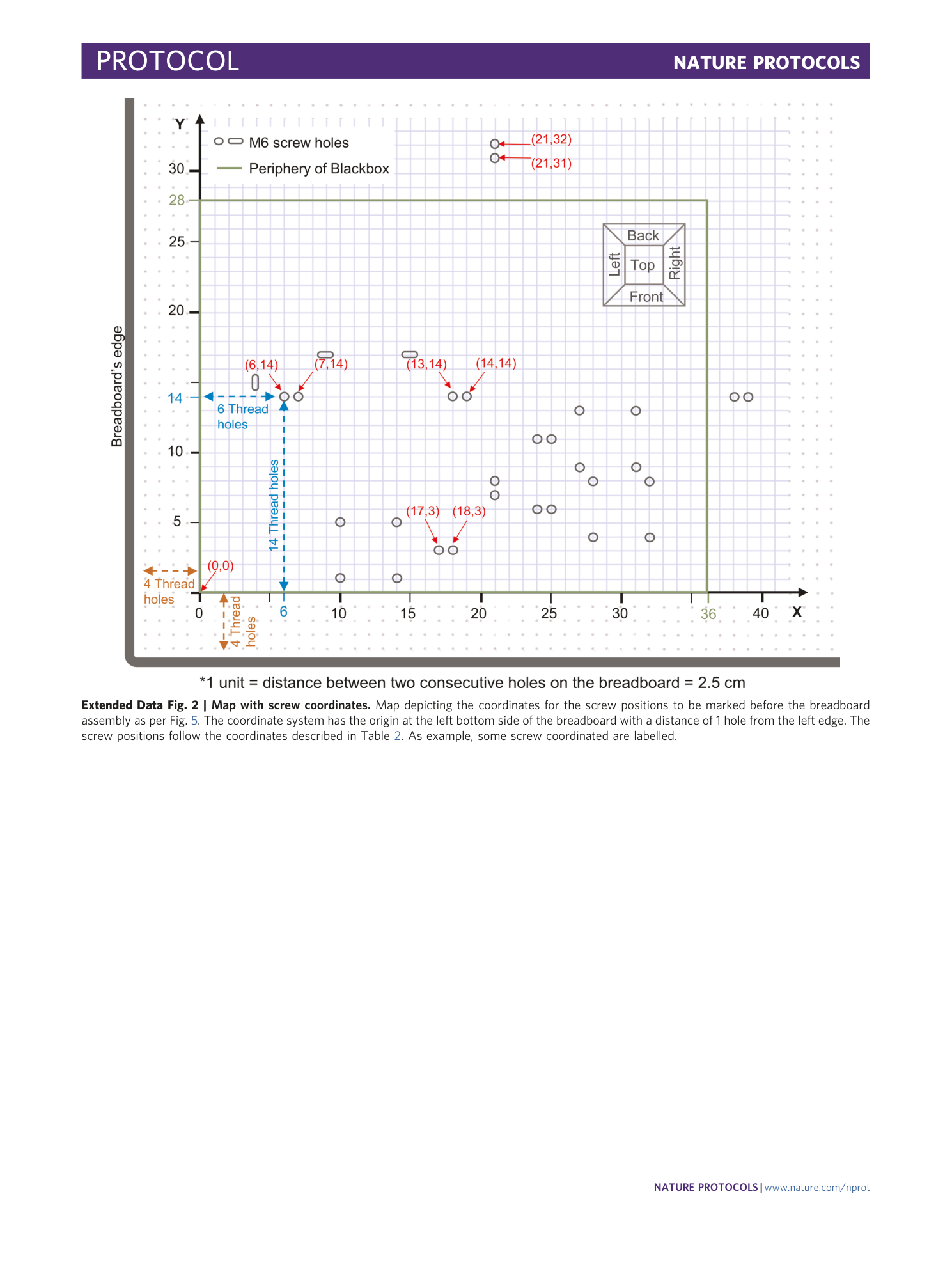
Extended Data Fig. 2 Map with screw coordinates.
Map depicting the coordinates for the screw positions to be marked before the breadboard assembly as per Fig. 5 . The coordinate system has the origin at the left bottom side of the breadboard with a distance of 1 hole from the left edge. The screw positions follow the coordinates described in Table 2 . As example, some screw coordinated are labelled.
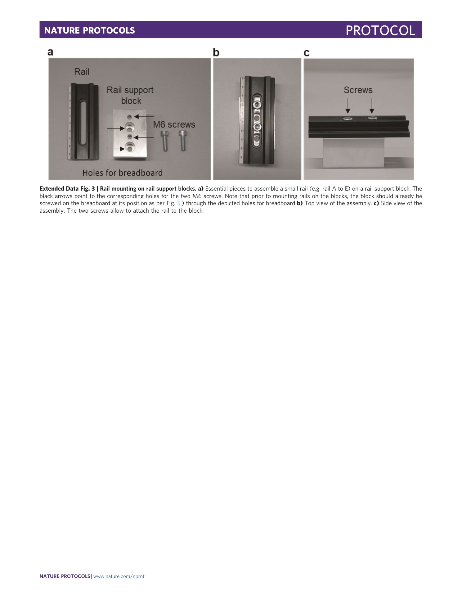
Extended Data Fig. 3 Rail mounting on rail support blocks.
a) Essential pieces to assemble a small rail (e.g. rail A to E) on a rail support block. The black arrows point to the corresponding holes for the two M6 screws. Note that prior to mounting rails on the blocks, the block should already be screwed on the breadboard at its position as per Fig. 5 .) through the depicted holes for breadboard b) Top view of the assembly. c) Side view of the assembly. The two screws allow to attach the rail to the block.
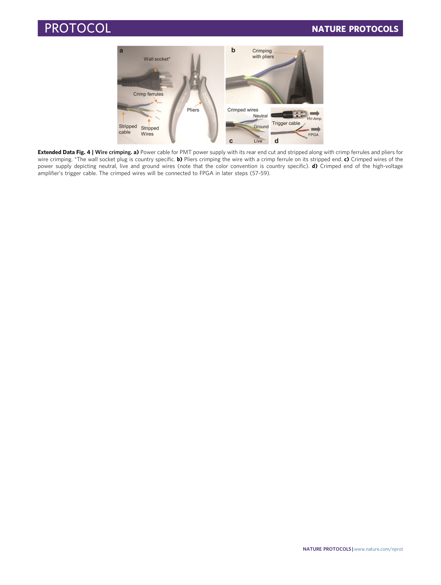
Extended Data Fig. 4 Wire crimping.
a) Power cable for PMT power supply with its rear end cut and stripped along with crimp ferrules and pliers for wire crimping. *The wall socket plug is country specific. b) Pliers crimping the wire with a crimp ferrule on its stripped end. c) Crimped wires of the power supply depicting neutral, live and ground wires (note that the color convention is country specific). d) Crimped end of the high-voltage amplifier’s trigger cable. The crimped wires will be connected to FPGA in later steps (57-59).
Extended Data Fig. 5 PMT wires.
The wires coming out of the PMT are assigned their function and pin number (in brackets) of the eight-pin connector. The cladding and core wire of the thick black cable are shown in zoom.
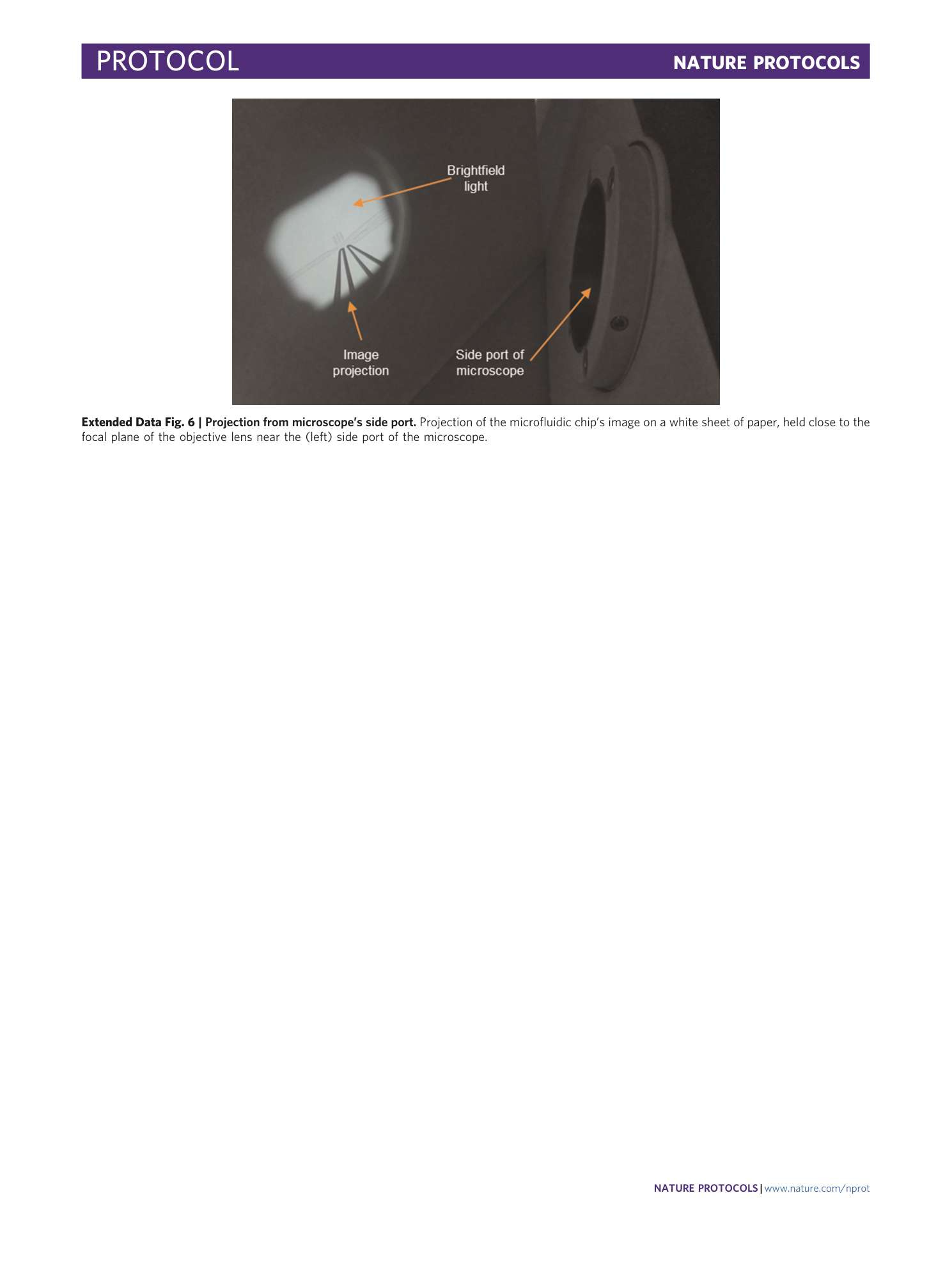
Extended Data Fig. 6 Projection from microscope’s side port.
Projection of the microfluidic chip’s image on a white sheet of paper, held close to the focal plane of the objective lens near the (left) side port of the microscope.
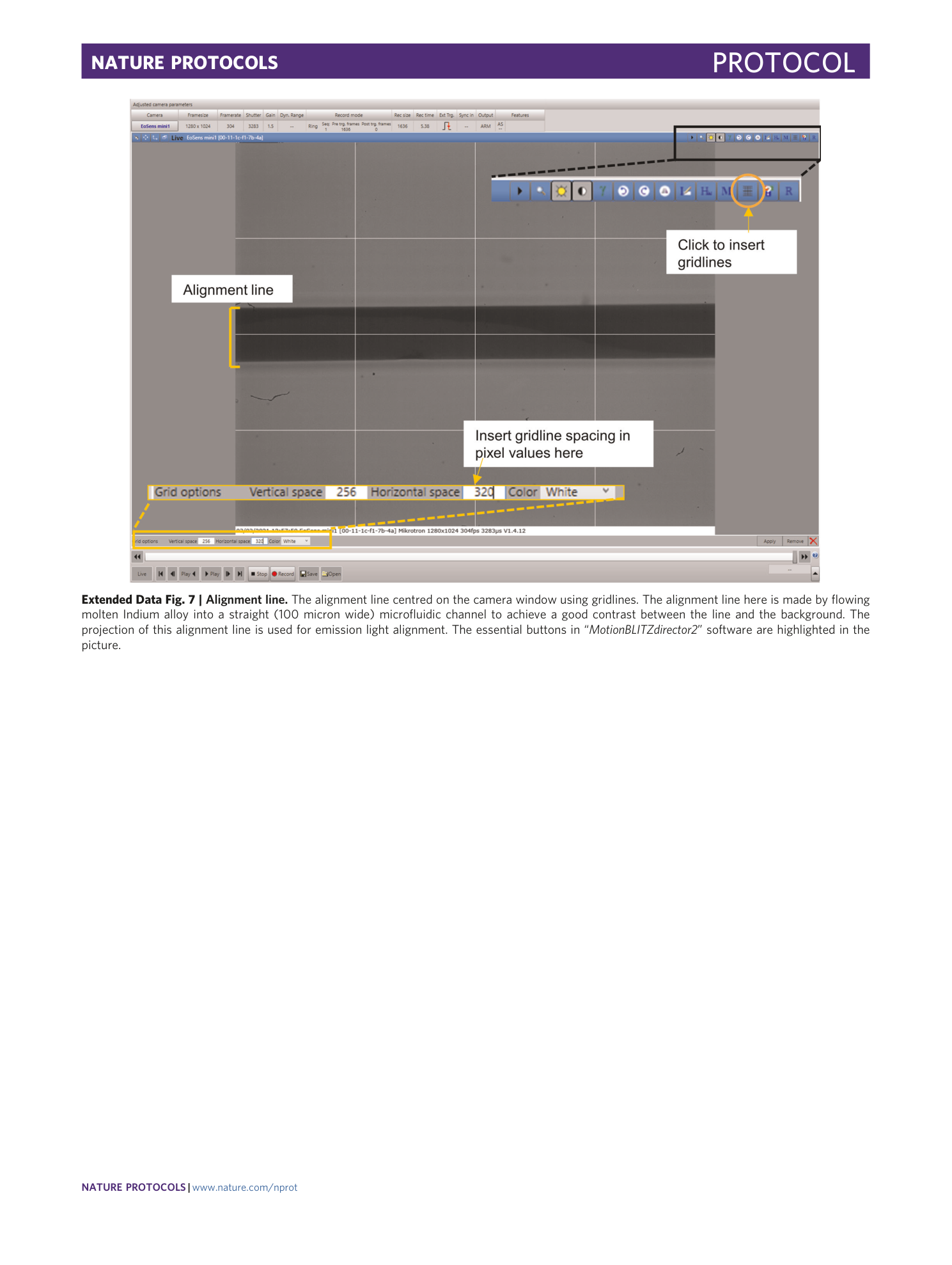
Extended Data Fig. 7 Alignment line.
The alignment line centred on the camera window using gridlines. The alignment line here is made by flowing molten Indium alloy into a straight (100 micron wide) microfluidic channel to achieve a good contrast between the line and the background. The projection of this alignment line is used for emission light alignment. The essential buttons in “ MotionBLITZdirector2 ” software are highlighted in the picture.
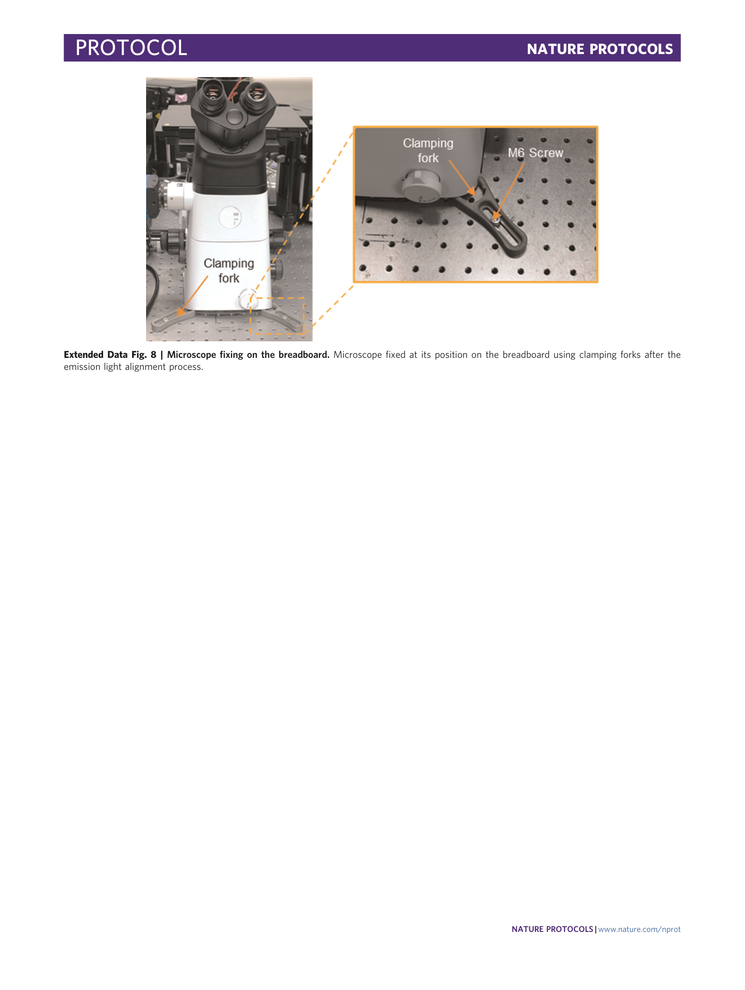
Extended Data Fig. 8 Microscope fixing on the breadboard.
Microscope fixed at its position on the breadboard using clamping forks after the emission light alignment process.
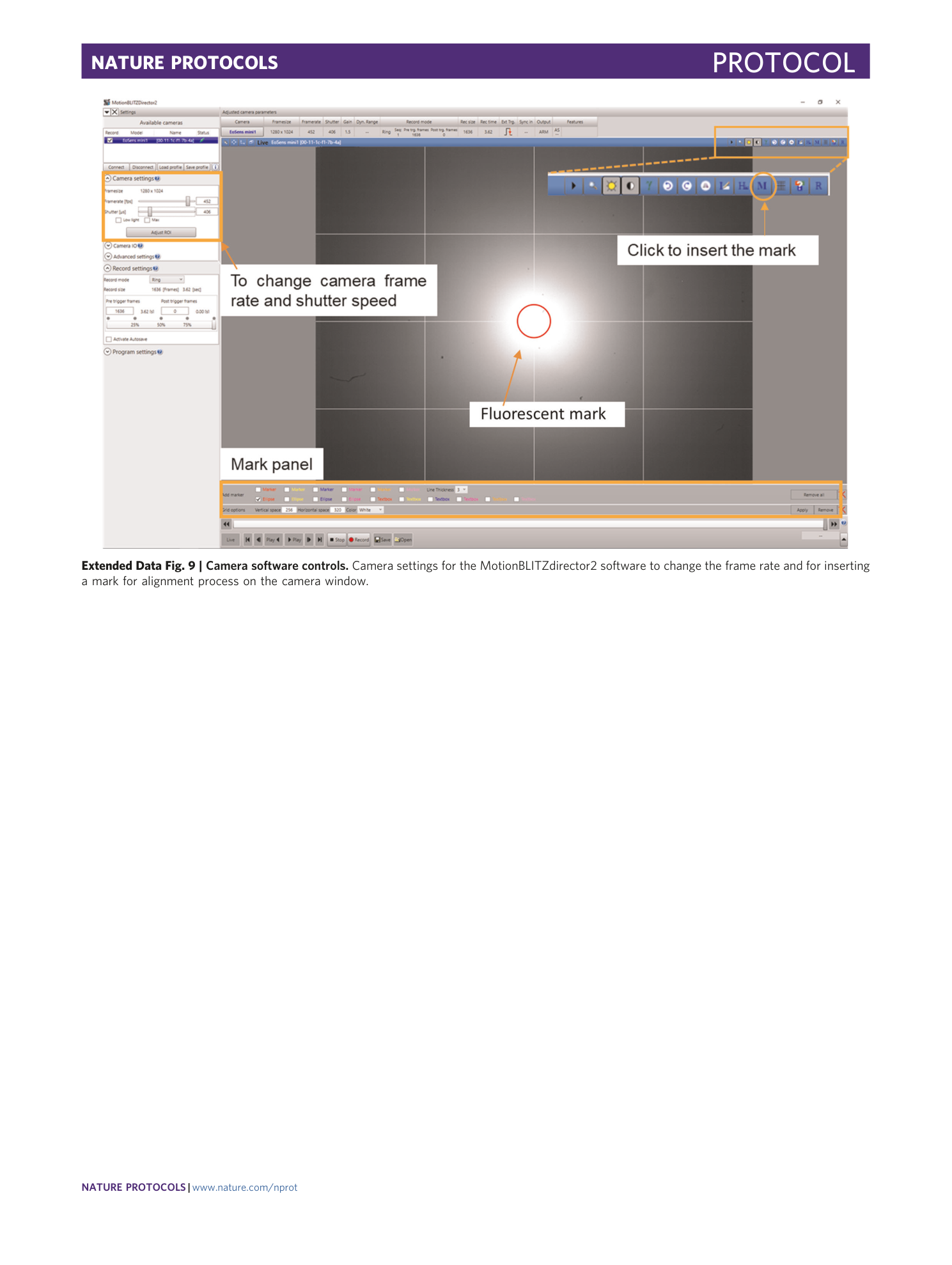
Extended Data Fig. 9 Camera software controls.
Camera settings for the MotionBLITZdirector2 software to change the frame rate and for inserting a mark for alignment process on the camera window.
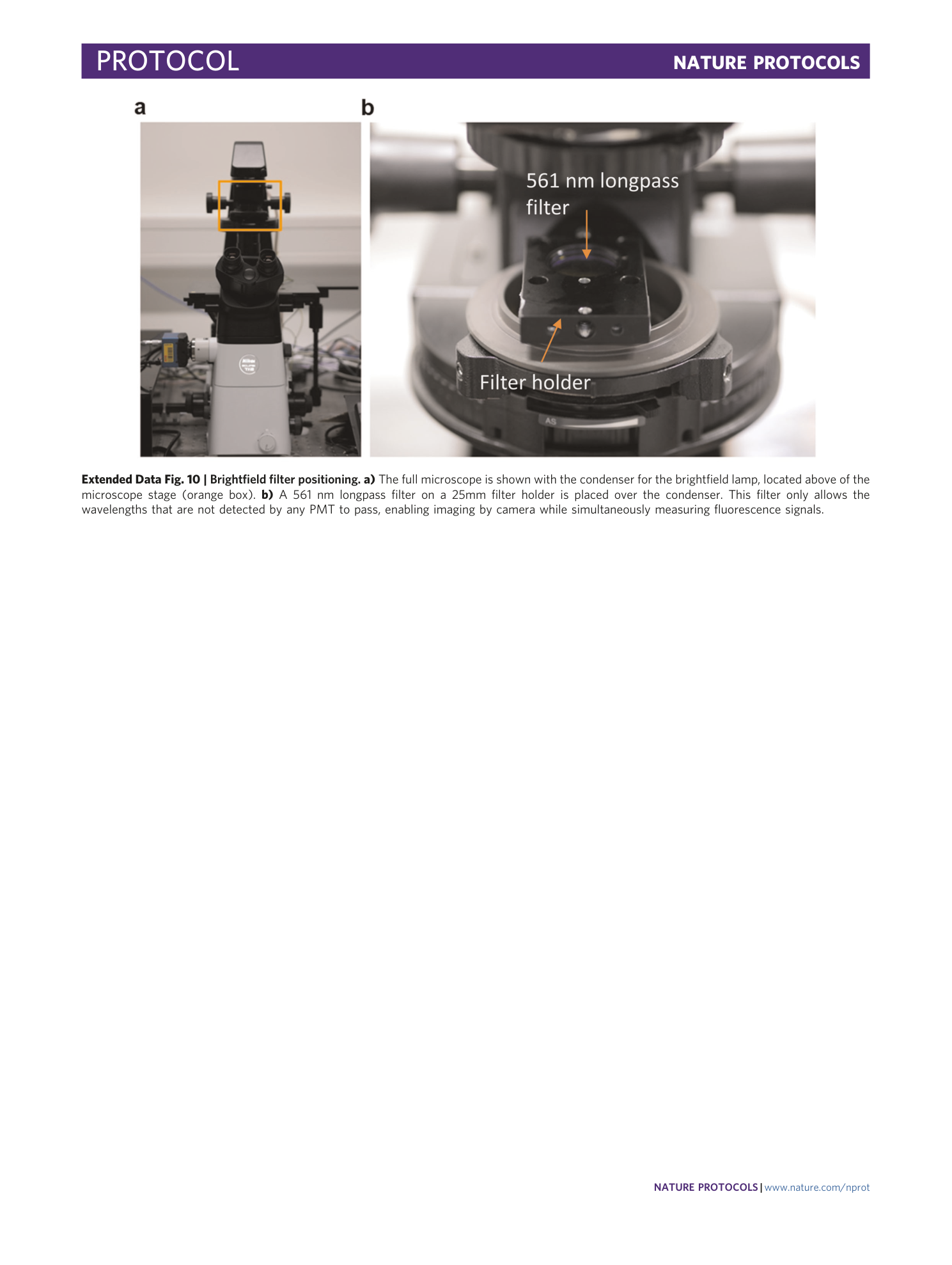
Extended Data Fig. 10 Brightfield filter positioning.
a) The full microscope is shown with the condenser for the brightfield lamp, located above of the microscope stage (orange box). b) A 561 nm longpass filter on a 25mm filter holder is placed over the condenser. This filter only allows the wavelengths that are not detected by any PMT to pass, enabling imaging by camera while simultaneously measuring fluorescence signals.
Supplementary information
Supplementary Information
Supplementary Figs. 1–9.
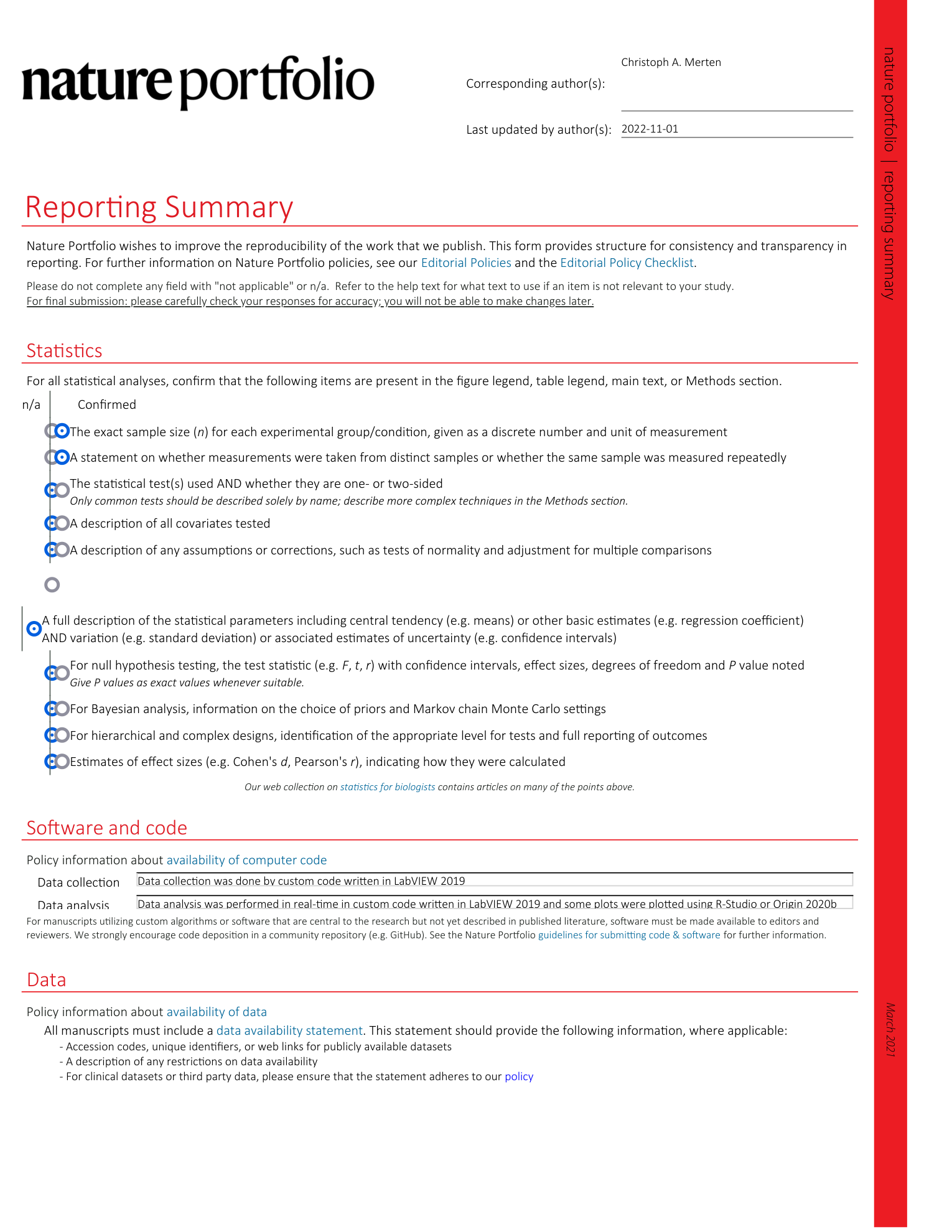
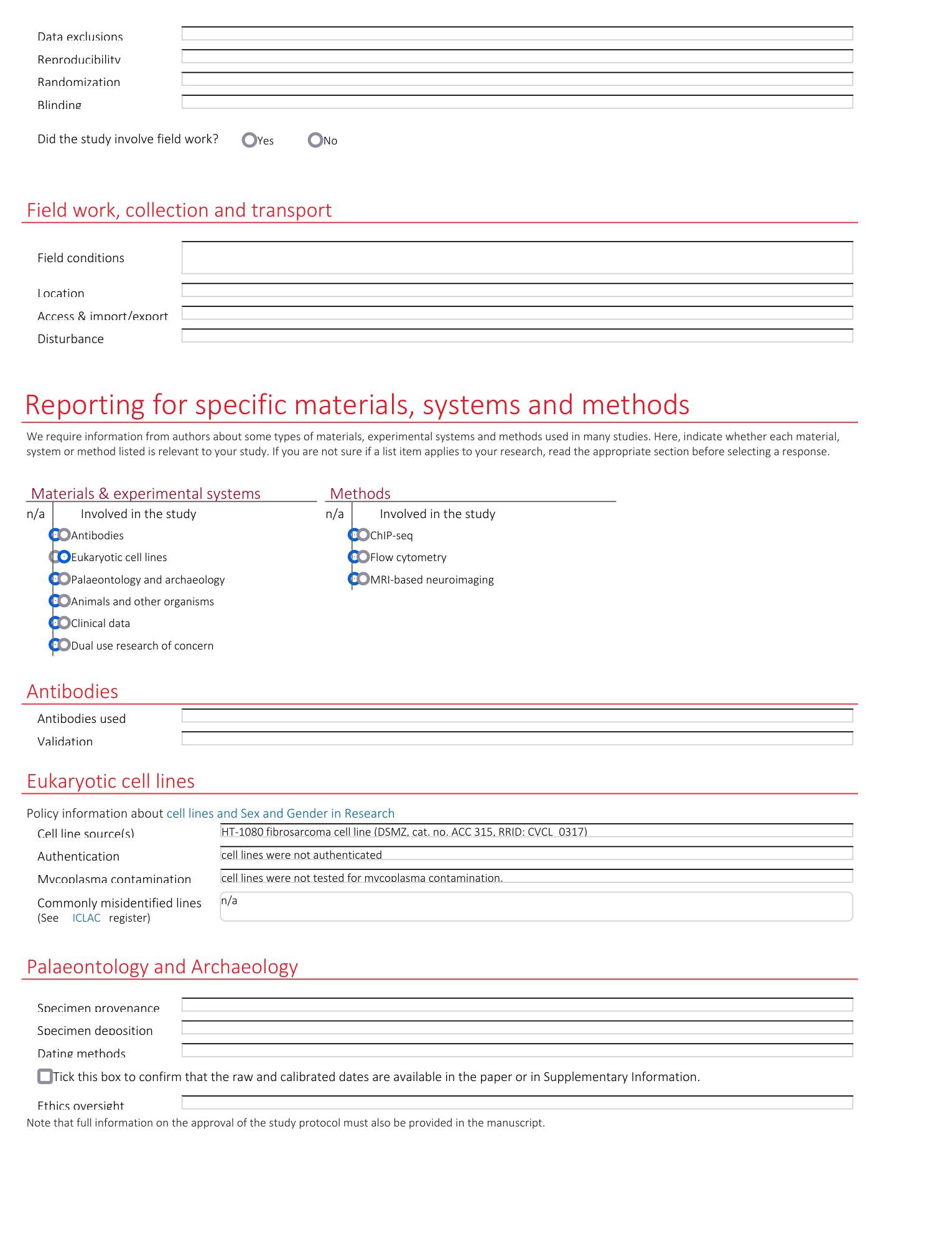
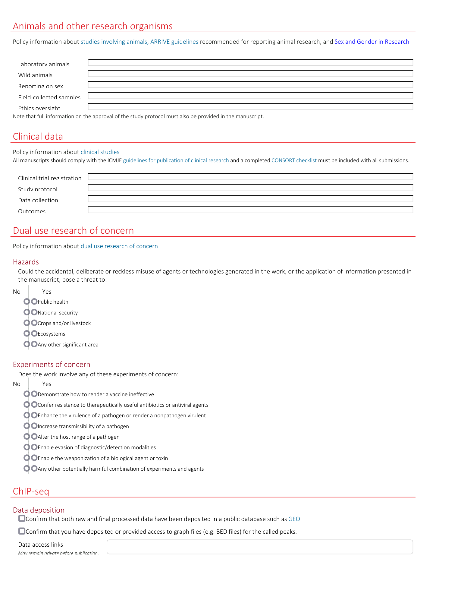
Reporting Summary
Supplementary Video 1
Animated video demonstrating breadboard assembly (Steps 1–68 of protocol).
Supplementary Video 2
Animated video demonstrating emission light alignment process (Steps 69–89 of protocol).
Supplementary Video 3
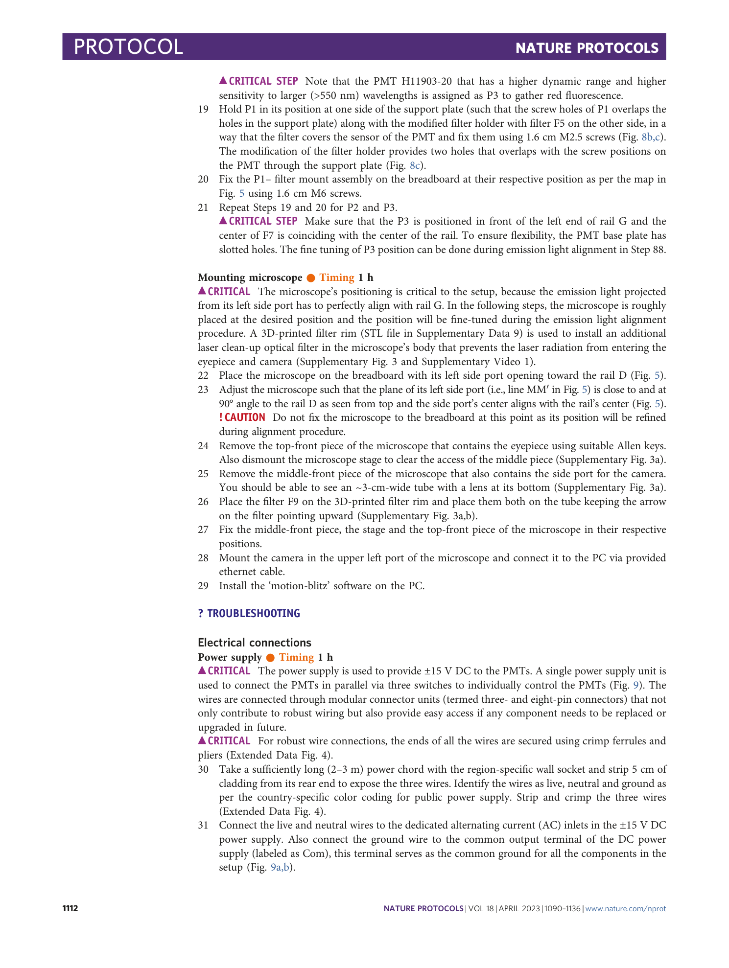
Animated video demonstrating laser alignment process (Steps 90–131 of protocol).
Supplementary Video 4
Video demonstrating how to operate TFADS software for droplet sorting.
Supplementary Video 5
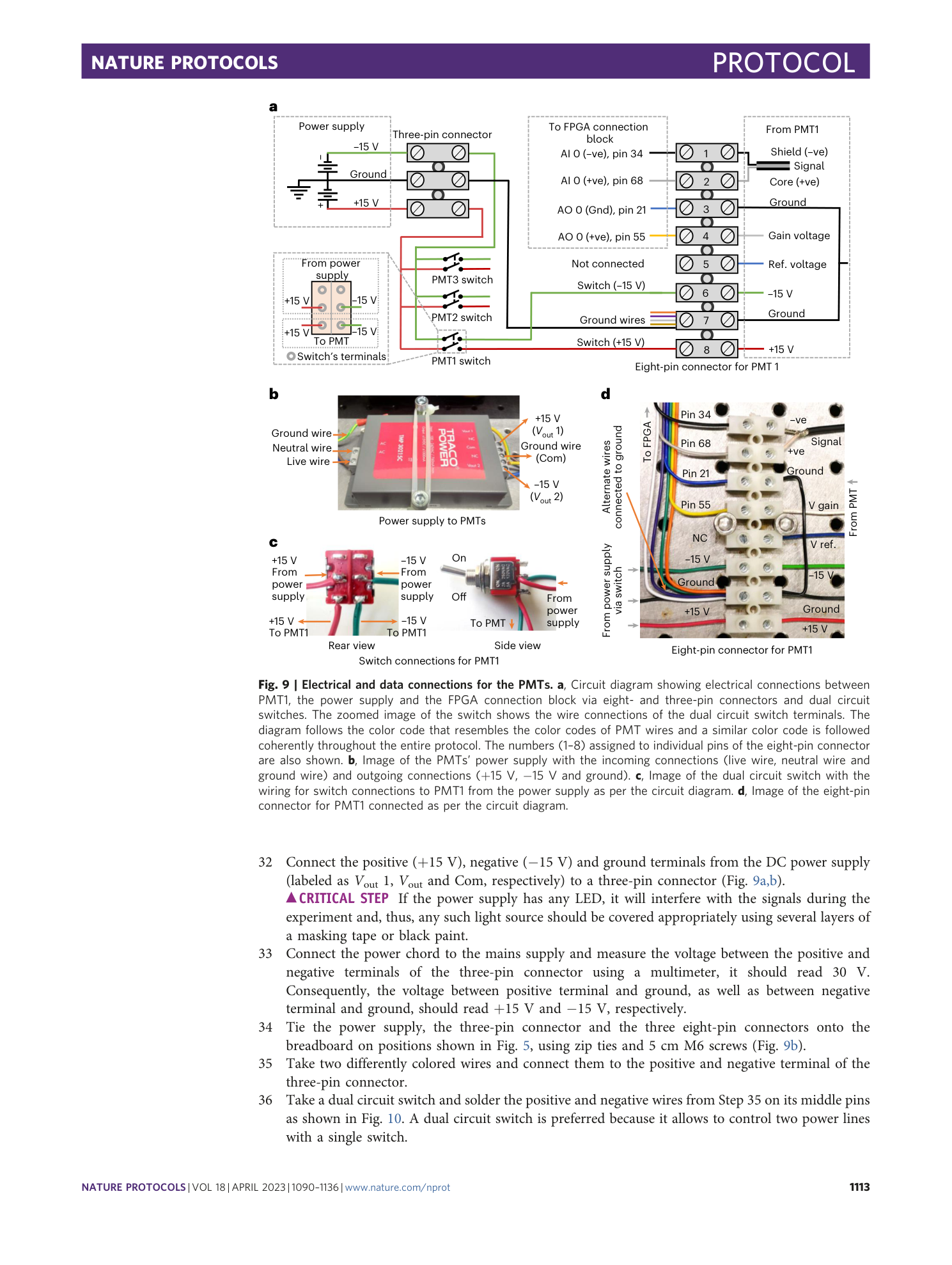
Video showing all the droplets in the microfluidic channel are going to the waste channel. This is expected to be the state of the system before starting the sorting operation.
Supplementary Video 6
Video showing effect of high-voltage amplitude on droplets during a sorting operation. The effects of 0.2 kV, 0.6 kV, 0.9 kV and 1.2 kV are shown.
Supplementary Video 7
Every third droplet going to collection channel when test ratio is 1 in 3. This shows that the high-voltage parameters are optimum and the system is ready for droplet sorting.
Supplementary Video 8
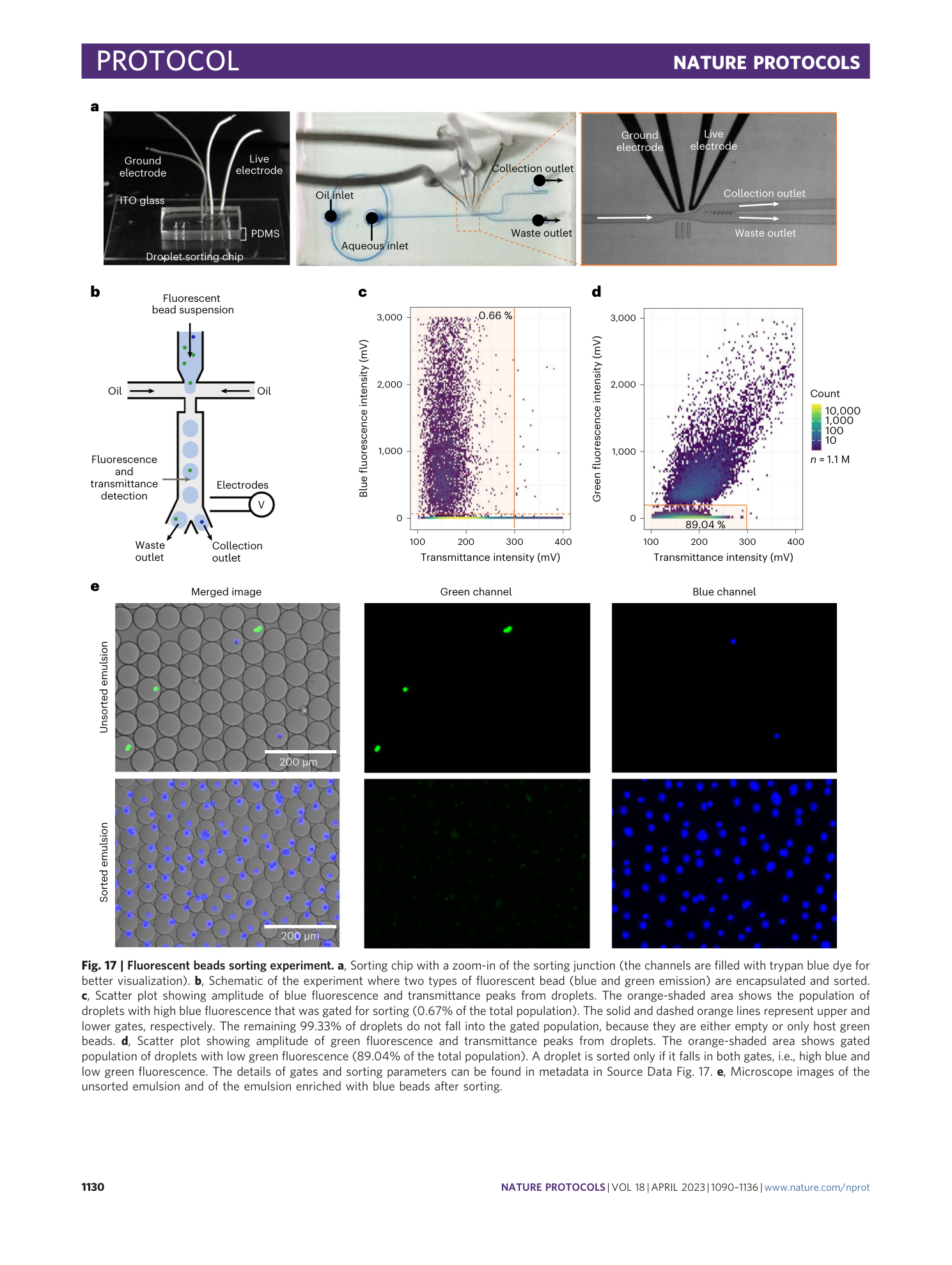
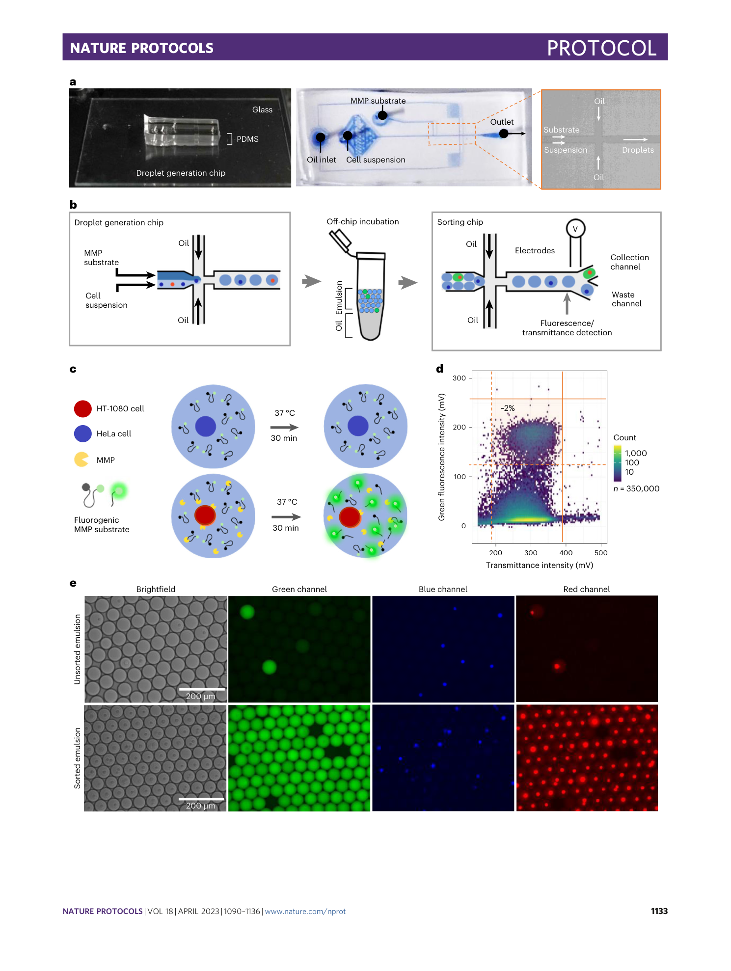
Sorting of a droplet that contains a blue fluorescent bead as discussed in Fig. 17.
Supplementary Video 9
Encapsulation of HeLa cells and HT-1080 cells in droplets using the microfluidic chip for droplet generating.
Supplementary Video 10
Reinjection of droplets into the droplet sorting chip after the off-chip incubation.
Supplementary Video 11
Sorting of a droplet with green fluorescence containing HT-1080 cells as discussed in Fig. 18.
Supplementary Software 1
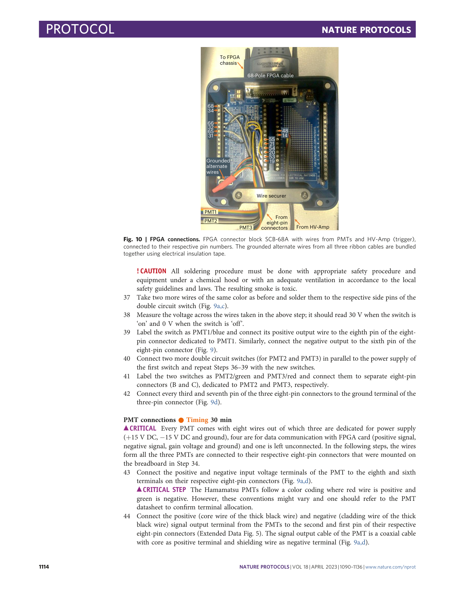
LabVIEW software for Transmittance and Fluorescence Activated Droplet Sorting (TFADS).
Supplementary Software 2
LabVIEW software for Transmittance and Fluorescence Activated Droplet Sorting (TFADS) with additional four PMT channels.
Supplementary Data 1
Design files for rail clamp modification.
Supplementary Data 2
Design files for filter holder modification.
Supplementary Data 3
CAD for rail support block.
Supplementary Data 4
CAD files for laser support block (M and FN series).
Supplementary Data 5
CAD files for PMT mount.
Supplementary Data 6
CAD files for black box parts.
Supplementary Data 7
STL files for 3D printing of target disk.
Supplementary Data 8
STL files for 3D printing of aperture disk.
Supplementary Data 9
STL files for 3D printing of filter rim.
Supplementary Data 10
CAD files for microfluidic chip fabrication (alignment line, droplet sorting chip and droplet generation chip).
Supplementary Data 11
Numeric data for Supplementary Fig. 6.
