Voronoi tesselation
Adalberto Merighi, Laura Lossi
Disclaimer
DISCLAIMER – FOR INFORMATIONAL PURPOSES ONLY; USE AT YOUR OWN RISK
The protocol content here is for informational purposes only and does not constitute legal, medical, clinical, or safety advice, or otherwise; content added to protocols.io is not peer reviewed and may not have undergone a formal approval of any kind. Information presented in this protocol should not substitute for independent professional judgment, advice, diagnosis, or treatment. Any action you take or refrain from taking using or relying upon the information presented here is strictly at your own risk. You agree that neither the Company nor any of the authors, contributors, administrators, or anyone else associated with protocols.io, can be held responsible for your use of the information contained in or linked to this protocol or any of our Sites/Apps and Services.
Abstract
This protocol describes how to perform Voronoi tesselation analysis of cerebellar images. It can be used for any biological images to study cellular sociology and is based on a model of parametrization and quantitation of
cellular population topographies developed by Marcelpoil and Usson (1992). It is advantageous to analyze cellular migration and dispersion in longitudinal studies.
Before start
Be sure to familiarize yourself with the theory of Voronoi tessellation
Steps
Image processing with the Voronoi generator
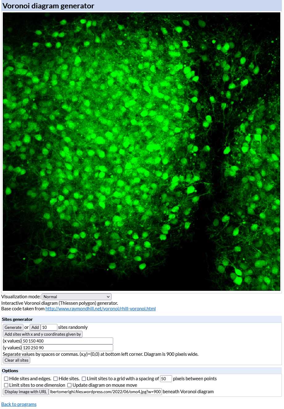
Open the interactive Voronoi diagram (Thiessen polygon) generator (https://cfbrasz.github.io/Voronoi.html).
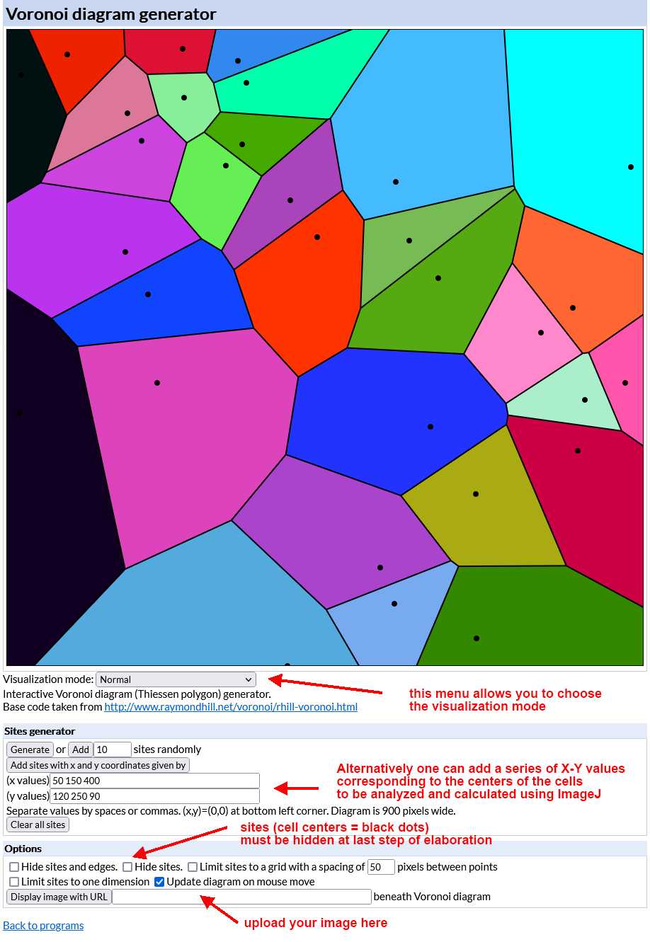
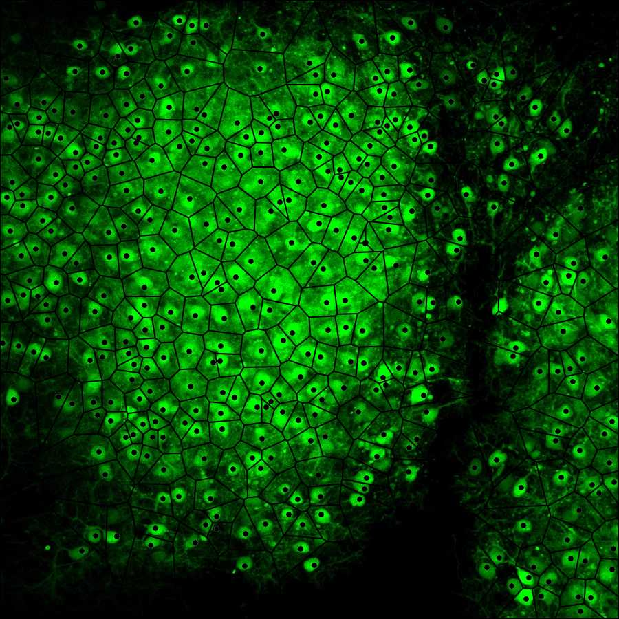
Upload the image to be analyzed as indicated in the figure above. To do so your image (size must be 900x900 pixels and preferably saved as a PNG file) has to be uploaded to the internet first so that it is possible to copy and paste its URL in the Voronoi generator. After uploading the generator displays the image in its working space as shown in the figure below.
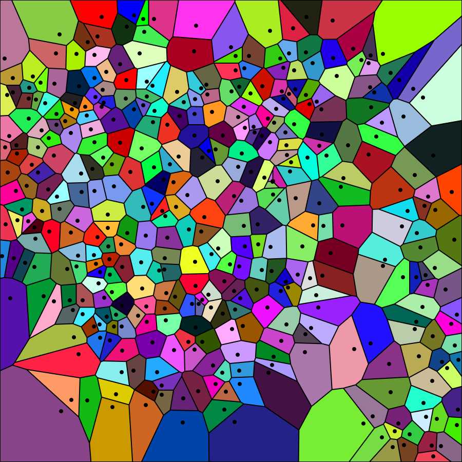
Choose "Visualization Normal" from the Visualization mode drop-down menu of the generator. The tesselation appears as shown in the image below. Again save the image on your computer (right-click on the image and choose "save" from the drop-down menu).
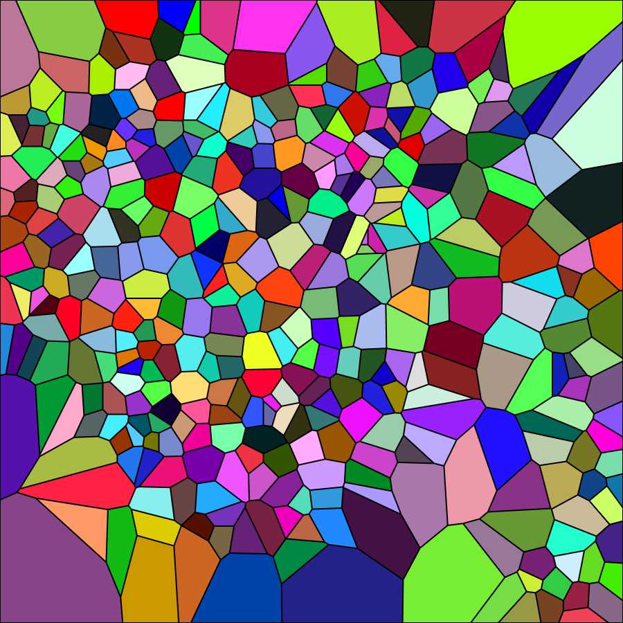
Select "Hide sites" from the Options menu of the generator. The tesselation appears as shown in the image below (black dots corresponding to cell centers disappear). Again save the image on your computer (right-click on the image and choose "save" from the drop-down menu).
Elimination of the marginal polygons with Photoshop
Due to the properties of the Voronoi partition, some polygons of the paving are not statistically representative of the set of polygons - see Marcelpoil, R.; Usson, Y. (1992) Methods for the study of cellular sociology: Voronoi diagrams and parametrization of the spatial relationships. Journal of Theoretical Biology 154 , 359-369.
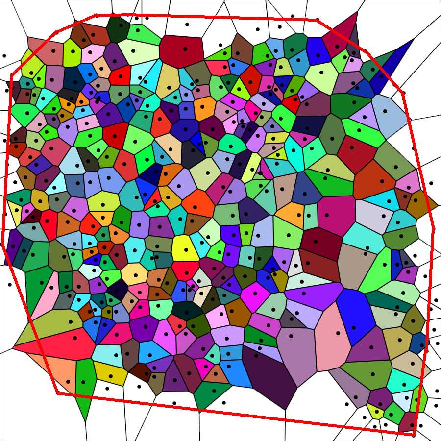
Those polygons are associated with points located on the border of the cell population and have one or more summits that do not contain total information on their "surround" ( marginal polygons ). Such summits are created by points that belong to a half-plane that does not contain this particular summit. Therefore, every point of the cell population whose associated polygon satisfies one of the two following conditions is not taken into account in the further calculations.
-
The polygon is open (the point belongs to the convex hull),
-
At Ieast one of the summits of the polygon is outside the convex hull.
Elimination of the open polygons is carried out with Photoshop using the Magic wand tool to select and cancel them from the image above named Elaboration 1, as shown in the image below.
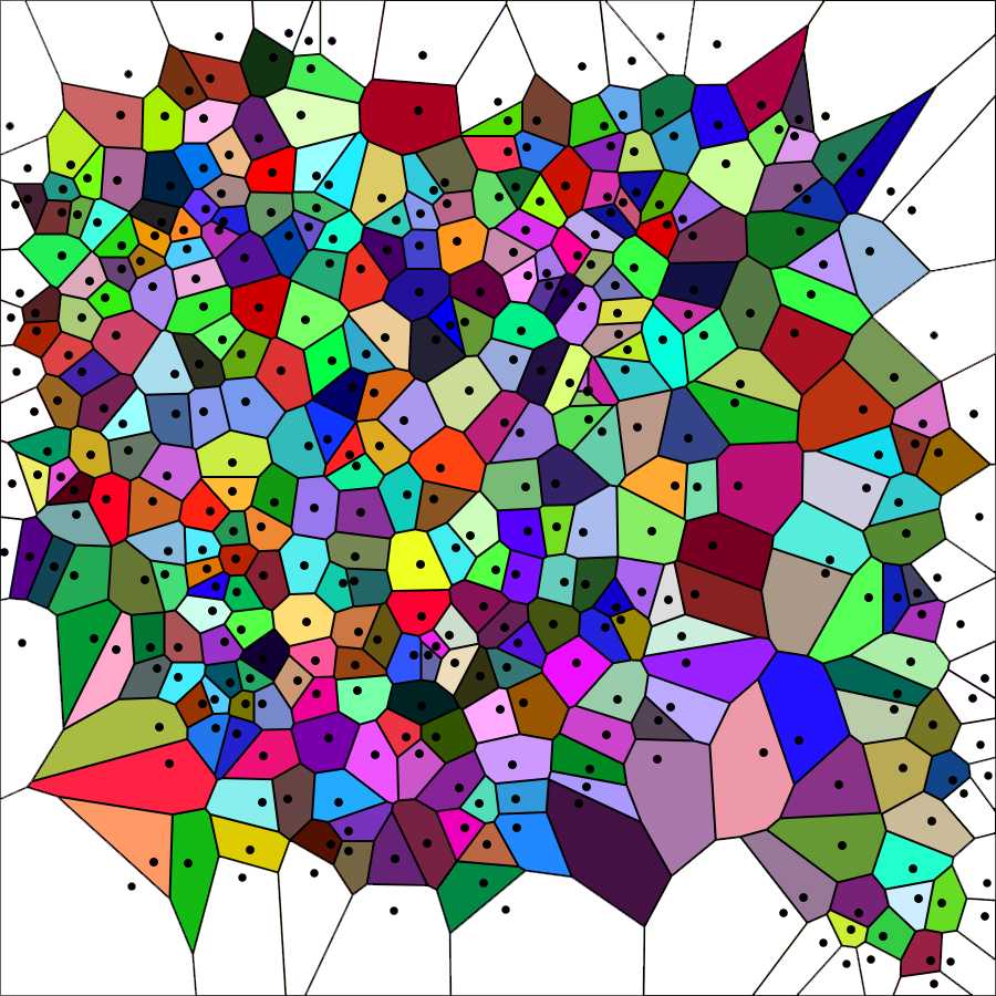
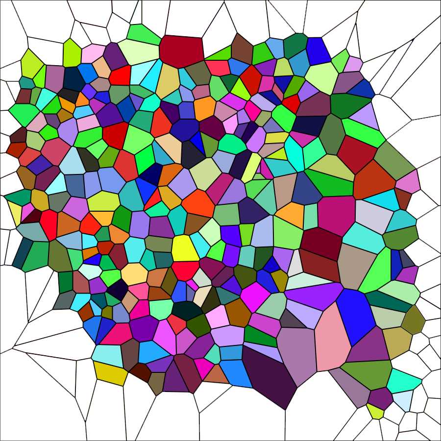
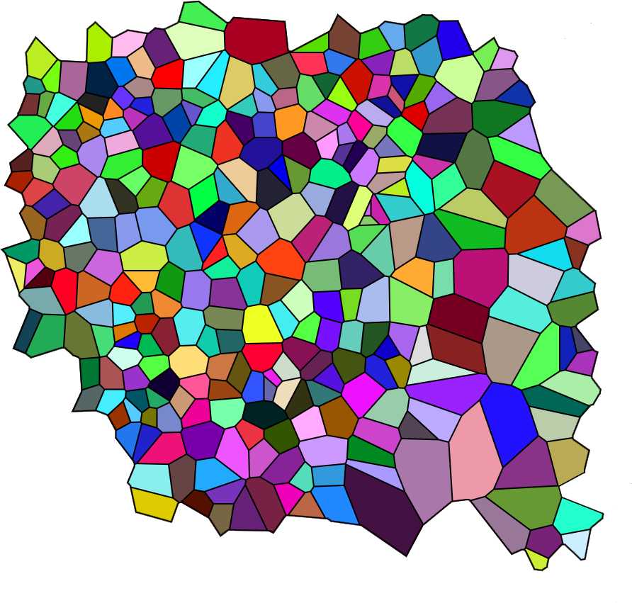
Cancel the sides of the marginal polygons. Use the Magic wand tool of photoshop followed by the commands Selection → Expand 2px; Selection → Contract 1px; Cancel ; Modify → Stroke (color black) 2px. You should obtain an image in which the area of the marginal polygons is empty as in the figure below. This is the last elaboration that will be used for the subsequent steps of analysis.
Analysis of Voronoi polygons with ImageJ
Open the image to be analyzed with ImageJ. Set the appropriate scale with Analyze → Set scale .
Run the following Macro by selecting Plugins → Macros → Run → Voronoi Macro
Voronoi Macro
run("Enhance Contrast...", "saturated=2");
run("8-bit");
run("Find Edges");
//run("Brightness/Contrast...");
setMinAndMax(0, 0);
run("Apply LUT");
run("Set Measurements...", "area perimeter shape limit display redirect=None decimal=6");
run("Analyze Particles...", "display summarize add in_situ");
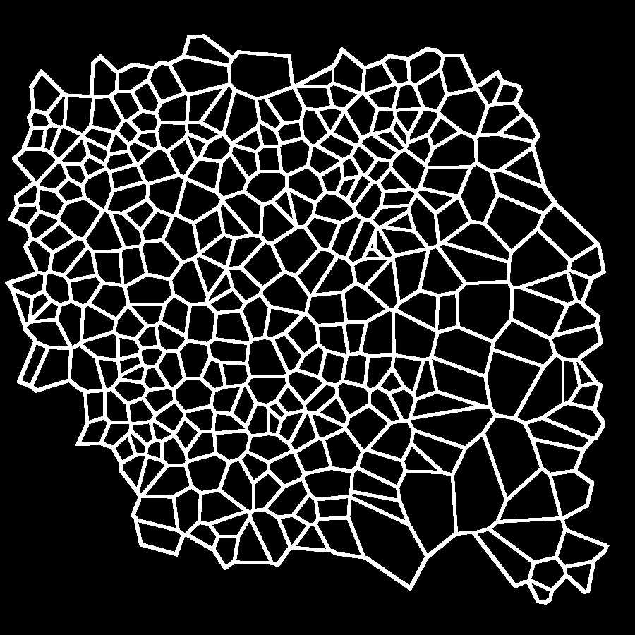
The macro enhances image contrast (optional), converts the image into a B&W 8-bit image, finds the edges of the Voronoi polygons, and optimizes their contrast as in the figure below.
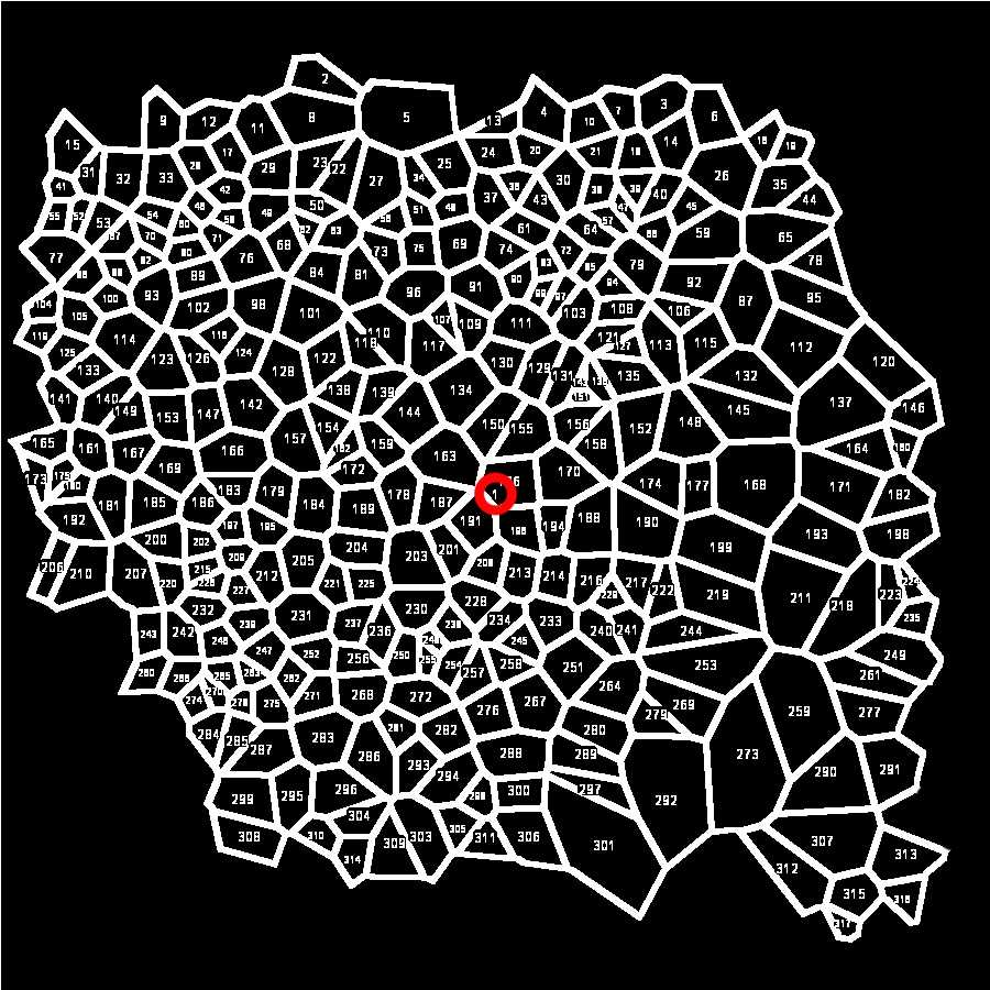
It then sets up the measurements necessary for the following analysis of polygons: Area , Shape descriptors , and Perimeter . It also permits the creation of an image (below) with the overlay indication of the individual polygons that the program has measured ( Add to overlay and Display label ). It finally sets the number of Decimal places to 6. When run, the Macro performs the command Analyze Particles .
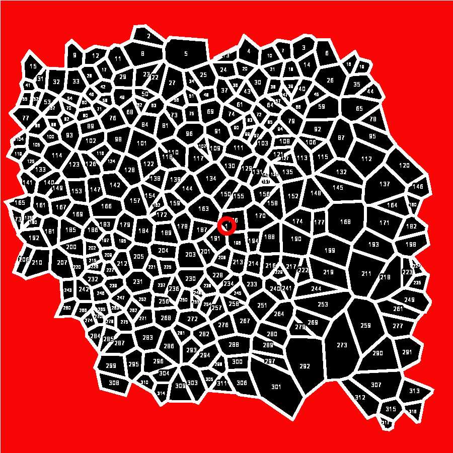
At the end of the Macro, all computed values are saved in a .csv or a .xls file (according to the version of ImageJ used) that must be converted into a .xlsx Excel file.
Analysis of data
Open the .csv or .xls file generated by ImageJ with Microsoft excel. The file appears as follows
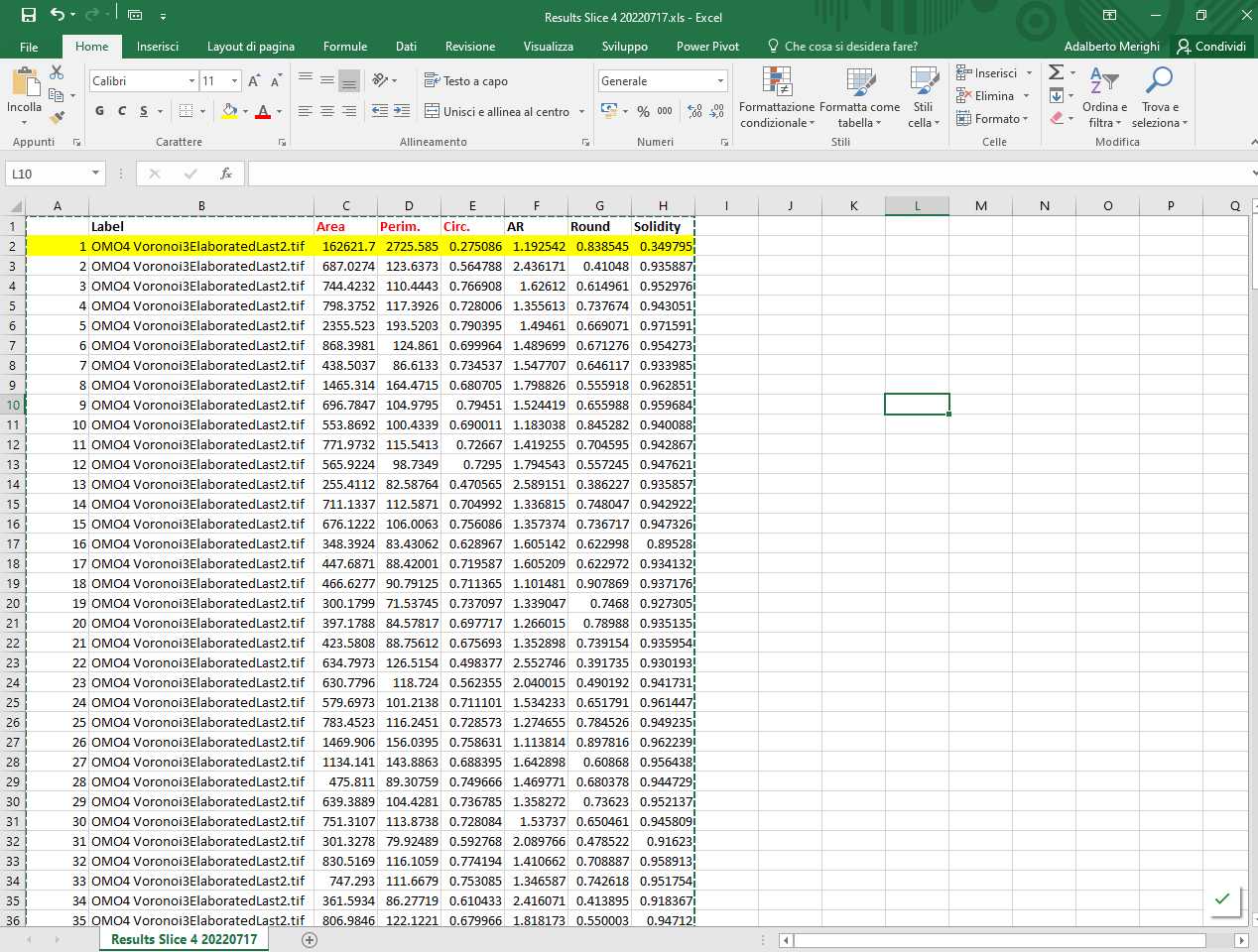
The file contains the following information: Column A: progressive numbering of the particles (polygons) counted by ImageJ; Column B: Identification of image analyzed; Column C: Area (in µm2 if the Set scale command has been set properly); Column D: Perimeter (in µm if the Set scale command has been set properly); Column E: Circularity (or Roundness factor); Columns F-H: Other shape descriptors computed by ImageJ that are not used in the analysis. Note that line 2 (highlighted in yellow) corresponding to Particle 1 must be deleted (as indicated above).
Save the file as a .xlsx file.
Open the .xlsx file in Excel and calculate the following:
-
Mean of area , perimeter , and circularity ( roundness )
-
Standard deviation Standard deviation of area , perimeter , and circularity ( roundness )
- Area Disorder (AD)
- Roundness Factor Homogeneity (RFH)
The mean circularity (roundness) ( RFav ) is computed directly by the ImageJ program using the following formula
where A(x) is the area and L(x) is the perimeter of the N polygons generated by the Voronoi generator. RFav is a pure number (0< RFav≤1).
The AD is calculated as follows:
where σA is the area standard deviation, and Aav is the mean area.
The RFH is calculated as follows:
where σRF is the roundness factor standard deviation, and RFav is the mean roundness factor.
Both are pure numbers with values >0 and ≤1.
Transfer the values of RFav, AD, and RFH to a new Excel spreadsheet for subsequent statistical analysis.
