Behavior Hardware Setup Protocol
Sasha Burwell
Abstract
This protocol details instructions for recreating the conditioning/extinction reward learning assay used in this paper.
Steps
Behavior Hardware Setup
Use the spray adhesive to attach egg crate foam to the inside walls and ceiling of the Med-Associates box. Though the box is already sound attenuating, this will help with further sound attenuation.
Set up the NI Card:
Place the NI USB-6351 card outside and adjacent to the Med-Associates box. This will allow for easy electrical connections, without potential damage from mice.
Use Velcro or tape to securely attach a breadboard next to or on top of the NI card.
Plug in the NI card to an outlet and the computer that will be running the MATLAB behavior code.
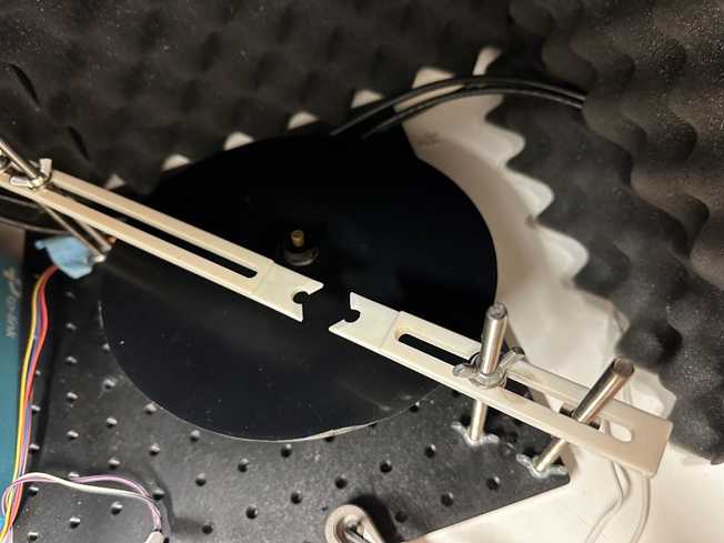
Build the treadmill:
On the 12x12 Thor Labs base, about 4-5” in from one corner, use the clamping fork to attach the studded pedestal base adapter to the base board.
Screw in the 1” post holder.
Attach the 2” optical post to the post holder.
Attach the swivel post clamp to the 2” optical post, and attach the 1” optical post to the other arm of the swivel clamp.
Screw this 1” optical post into the hole on the side of the rotary encoder.
Drill a small hole, the same size as the arm of the rotary encoder, into the direct center of the Plexiglas disk.
- Place the Plexiglas disk, such that it is tightly fitting and has no wiggle room, atop the arm of the rotary encoder.
- The rotary encoder arm should rotate when the Plexiglas disk is spun. If needed, use a 3D printed adapter to securely connect the two components.
Cut a small hole into the center of the silicon rubber sheet (to accommodate the rotary encoder arm), and place the silicon sheet on top of the Plexiglas disk to create a grippy surface for the treadmill.
Attach the 5-pin connector to the rotary encoder, with the other side leaving the box to connect to the NI card.
- Blue wire: to PFI8/P2.0
- Yellow wire: to PFI10/P2.2
- Orange wire: to +5V
- Brown wire: to ground
- Purple wire: unused
From these instructions, you should have a horizontal treadmill that can rotate with the rotary encoder and angle slightly in the horizontal plane, such that the mice are running slightly uphill.
Build the head-fixation apparatus:
In line with your treadmill, screw 2 7” stainless steel rods into the 12x12 base board on either side of the treadmill (4 total).
- Per side, place 1 rod as close to the treadmill as possible without touching it, and the other 2 peg holes away. Attach firmly to the base board with wing nuts.
Using hex nuts and washers, place the 3D printed head posts onto the stainless steel rods such that they meet over one side of the circular treadmill.
- The longer head post will cross the majority of the treadmill. Both head posts should be about 4-5” above the base board, therefore clearing the treadmill at the rough height of a mouse.
Use more washers and wing nuts to hold the head posts firmly in place. These can be loosened and tightened when head-fixing a mouse, and can be moved up and down the steel rods for height flexibility.
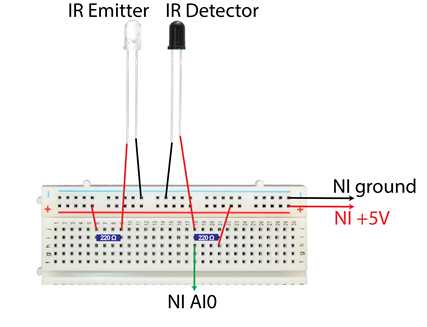
Build the infrared lick detection system:
On the 12x12 Thor Labs base, to the front left of the treadmill, use the clamping fork to attach the studded pedestal base adapter to the base board.
Screw in the 3” post holder.
Attach the 6” optical post to the post holder.
Attach the swivel post clamp to the 6” optical post, and attach the 4” optical post to the other arm of the swivel clamp.
Screw this 4” optical post into the small hole on the side of the 3D printed lick port.
The lick port has two additional holes at the front of the u-shape. Insert an IR emitter bulb into one, and an IR detector bulb into the other, such that they face each other.
IR detector: attach the long wire to ground, and the shorter wire to the NI card AI0 port and +5V using a 220Ω resistor (see below wiring diagram).

IR emitter: attach the short wire to ground, and the long wire to +5V using a 220Ω resistor (see below wiring diagram).
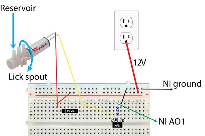
Build the reward delivery system:
Use glue to clog the innermost port of the 3 port solenoid.
Use Velcro to attach the solenoid, ports facing outwards, to the side of the Med-Associates Box.
Use Velcro to attach the 60mL Luer Lock syringe above the level of the lick port (this is your liquid reservoir; if it is above the lick spout, gravity will pull the liquid through to the lick spout whenever the solenoid is open).
Attach one side of the On/Off valve to the Luer Lock syringe, and the other to the stainless steel dispensing needle.
Using an appropriately cut length of PVC clear tubing, connect the dispensing needle of the reservoir to the outermost port of the solenoid.
Cut a longer length PVC clear tubing (needs to reach from solenoid to lick port) and attach the stainless steel tubing to one end. This will be the lick spout. Connect the other end of the PVC tubing to the middle port of the solenoid.
Put the stainless steel lick spout through the hole crossing through the middle of the “u” of the lick port, and use a thumbscrew through the top of the lick port to hold it in place.
Connect the solenoid to the NI card (see the below circuit diagram):
- Use a 12V power cable and the screwturn DC power jack adapter to create a 12V input to one of the solenoid connections.
- Wire the other solenoid connection to the +12V using a diode, and to the C arm of a NPN transistor.
- Wire the E arm of the transistor to ground.
- Wire the B arm of the transistor to a 330Ω resistor, and connect this to the AO1 output port on the NI card.
- Connect AO1 on the NI card to the AI2 input port, to read the solenoid output into the MATLAB code.
Set up the speaker:
Plug the speaker into an outlet, and place in the Med-Associates box in front of the treadmill.
Plug in one end of the audio cable to the speaker.
To have the MATLAB code control the speaker output, attach the other end of the audio cable to the NI card using alligator clips and male-male jumper cables.
- Connect the audio cable ground to AO GND on the NI Card.
- Connect the audio cable input to both AI3 and AO0 on the NI Card.

Set up the Basler ace camera:
Connect the camera to the lens, tripod mount, and tripod.
Plug the camera in to an outlet and to the computer running the MATLAB code, and set in the Med-Associates box angled so that the mouse and lick port can be readily viewed.
Plug in the Bosch IR Illuminator, and place near the camera so that it illuminates the treadmill setup.
Connect P0.0 on the NI Card to AI9 to create an end of trial flag for the MATLAB code.
