Surgical Procedure for Implantation of Opto-Array in Nonhuman Primates
Reza Azadi, Reza Azadi, Simon Bohn, Simon Bohn, Mark A. G. Eldridge, Mark A. G. Eldridge, Arash Afraz, Arash Afraz
Abstract
Optogenetics allows precise temporal control of neuronal activity in the brain. Engineered viral vectors are routinely used to transduce neurons with light-sensitive opsins. However, reliable virus injection and light delivery in animals with large brains, such as nonhuman primates, has proven challenging. The Opto-Array is a novel yet simple device that is used to deliver light to extended regions of the cortex surface for high-throughput behavioral optogenetics in large brains. Here we present protocols for surgical delivery of virus (Basic Protocol 1) and implantation of the Opto-Array (Basic Protocol 2) in two separate surgeries in a rhesus monkey's inferior temporal cortex. As a proof of concept, we measured the behavioral performance of an animal detecting cortical optogenetic stimulations (Basic Protocol 3) with different illumination power and duration using the Opto-Array. The animal was able to detect the optogenetic stimulation for all tested illumination powers and durations. Regression analysis also showed both power and duration of illumination significantly modulate the detectability of the optogenetic stimulation. The outcome of this approach is superior to the standard practice of injecting and recording through a chamber for large areas of the cortex surface. Moreover, the chronic nature of the Opto-Array allows perturbation of neuronal activity of the same site across multiple sessions because it is highly stable; thus, data can be pooled over months. The detailed surgical method presented here makes it possible to use optogenetics to modulate neuronal activity across large regions of the cortex surface in the nonhuman primate brain. This method also lays the groundwork for future attempts to use optogenetics to restore vision in humans. © 2023 The Authors. Current Protocols published by Wiley Periodicals LLC.
Basic Protocol 1 : Virus injection surgery
Basic Protocol 2 : Opto-Array implantation surgery
Basic Protocol 3 : Cortical Perturbation Detection (CPD) task behavioral training
INTRODUCTION
Optogenetics entered systems neuroscience about a decade ago as a promising new technique for perturbing neural activity using light (Bernstein and Boyden, 2011; Fenno, Yizhar, and Deisseroth, 2011). Optogenetic modulation typically requires the injection of a viral vector carrying an opsin gene which, when expressed, confers the ability to alter neuronal activity with a particular wavelength of light. The advantages of optogenetics over traditional methods of neural perturbation (such as electrical microstimulation) include the ability to both activate and inactivate neurons with high temporal precision, targeting specific cell types and targeting the projections of a given brain area to another (Diester et al., 2011; Han, 2012). During the past decade, optogenetics has gradually claimed a solid position among the mainstream techniques of neural perturbation in the study of small brains (e.g., rodents), however, the application of optogenetics in large brains (such as in nonhuman primates) has been challenging (El-Shamayleh and Horwitz, 2019; Galvan et al., 2017; Gerits and Vanduffel, 2013; Gerits et al., 2012; Tremblay et al., 2020), a challenge that raises questions about the usefulness of optogenetics for therapeutic applications in human brains. A major problem in nonhuman primate optogenetics is the scarcity of chronically implantable platforms that are capable of reliable and scalable delivery of light into the cortical tissue.
In order to address this problem, we recently developed the Opto-Array, a chronically implantable array of 24 LEDs and a thermal sensor configured in a 5 × 5 matrix for delivering light to large brains, specifically nonhuman primates. Each LED is able to illuminate ∼1 mm2 of the cortical surface, allowing illumination of up to ∼5 × 5 mm of the cortex (Rajalingham et al., 2021). The chronic nature of the Opto-Array allows reliable perturbation of neural activity at the same site in electrophysiology and behavioral studies, in which data must be collected and pooled over months (Azadi et al., 2022; Azadi et al., 2023; Lafer-Sousa et al., 2023; Rajalingham et al., 2021). Moreover, compared with acute methods such as using optical fibers or direct illumination, a chronically implantable light delivery device reduces the risk of tissue damage and infection from open cranial chambers. In this article we explain the surgical techniques and procedures for Opto-Array implantation in macaque monkeys. We typically perform two separate surgeries; in the first surgery (Basic Protocol 1), we perform virus injection using an injector array. After a period of 4 to 8 weeks, the second surgery takes place, in which we confirm virus expression and implant the Opto-Array (Basic Protocol 2). Finally, we explain how to behaviorally train a macaque monkey to detect optogenetic cortical stimulation (Basic Protocol 3).
NOTE : All protocols involving animals must be reviewed and approved by the appropriate Animal Care and Use Committee and must follow regulations for the care and use of laboratory animals.
NOTE : Manufacturer, model, and ordering information for all major materials are described in Table S1. Item numbers in Materials Lists and protocol steps correspond to the table listings.
Basic Protocol 1: VIRUS INJECTION SURGERY
The purpose of this protocol is to detail the steps required to express opsin in the tissue of a macaque monkey brain, such that light can be used to manipulate neuronal activity. Choosing a virus is an essential part of the experimental design. We have found success with adeno-associated virus serotype 5 (see Tremblay et al., 2020 for a review of virus types in non-human primate optogenetics). The choice of viral payload will be determined by what experimental manipulation is being performed (inhibition or activation) as well as the kinetics of the manipulation (Mattis et al., 2011). For instance, Channelrhodopsin-2 (hChR2) and a chimeric opsin variant (C1V1) have been used to stimulate neural activity, and Archaerhodopsin-3 (ArchT) and Jaws have been used to inhibit neural activity in nonhuman primates (Tremblay et al., 2020). In order to verify viral expression, it is essential to choose a virus that causes cells expressing its optogenetic payload to coexpress a fluorescent indicator such as enhanced yellow fluorescent protein (eYFP), green fluorescent protein (GFP), or mCherry.
Materials
- Virus
- Head holder (item #1)
- Surgical blades #15 and #11
- Periosteal elevator (item #2)
- Adson tissue forceps
- Hemostats 5″ and 3.5″
- Mayo scissors
- Bone Rongeur
- Bone wax
- Surgical patties (item #3)
- Absorbable suture (e.g., Vicryl 3-0)
- Surgical drill
- Circular cutting wheel (item #4)
- Drill bit (item #5)
- Surgical spoon (item #8)
- Frazier dura hook
- Fine forceps
- Iris scissor
- Braided suture lines (e.g., silk/Vicryl 5-0)
- Injector array (Fredericks et al., 2020)
- Sterile transparent film (item #9)
- Artificial dura (item #10)
- Absorbable braided suture lines (e.g., Vicryl 5-0)
- Non-absorbable sutures for this procedure (e.g., Ethilon 3-0)
- Grooved surgical spoon (item #8)
- Bone putty (item #11)
Head stabilization
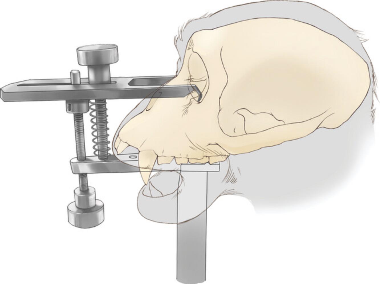
1.Use a low-profile head holder (Jerry-Rig USA, item #1) to stabilize the animal's head (Fig. 1).
Incision
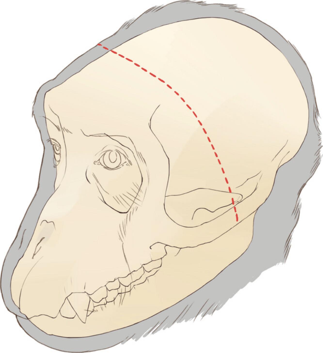
2.Perform a long coronal incision on the skin crossing zygomatic arches on both sides (Fig. 2) using a surgical blade (#15).
3.Separate the skin margin from the fascia using a periosteal elevator (item #2) while holding the skin margin with Adson tissue forceps.
4.Apply retraction to the skin by placing five large hemostats (5″) on each side of the margin, evenly spaced.
5.Make an incision in the fascia parallel to the skin margin with the same blade.
6.Similar to skin, apply retraction to the fascia by placing five small hemostats (3.5″) to each side of the margin, evenly spaced.
Skull exposure
7.Removing the zygomatic arch allows us to fully reflect the temporalis muscle and expose the temporal bone. To expose the arch, make a 10-15 mm incision in the temporalis muscle fascia covering the arch.
8.Use a periosteal elevator to detach the muscle and fascia attachments from the arch.
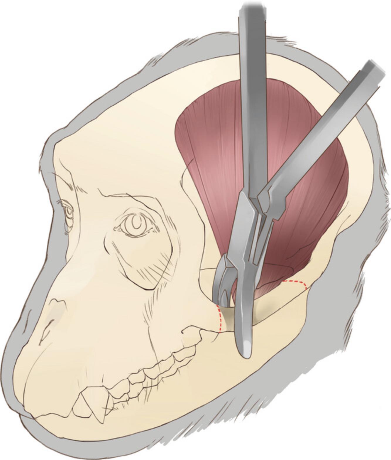
9.Extract the zygomatic arch. After isolating the arch, cut both ends using a bone rongeur and extract the arch (Fig. 3). Then, use the tip of the rongeur to remove all the remaining parts of the arch on the zygomatic bone and temporal bone.
10.Use bone wax to stop osteal bleeding After applying bone wax to the bleeding bone edges, use a periosteal elevator and a 5 × 20 mm piece of surgical patties (item #3) to firmly press the wax against the bone orifices.
11.Close the fascia incision over the arch with an absorbable suture (e.g., Vicryl 3-0) with a simple continuous or interrupted suture pattern.
12.Now the temporal bone can be exposed by detaching the temporalis muscle from its origins on the dorsal aspect of the skull. Use the sharp edge of a periosteal elevator to detach the dorsal part of the temporalis muscle from the periosteum of the parietal and frontal bones. To detach the body of the muscle, gently retract the muscle away from the bone using Adson forceps and detach it by moving the elevator horizontally (rostrocaudal) along the attachment line to keep the muscle capsule intact as it is separated from the bone.
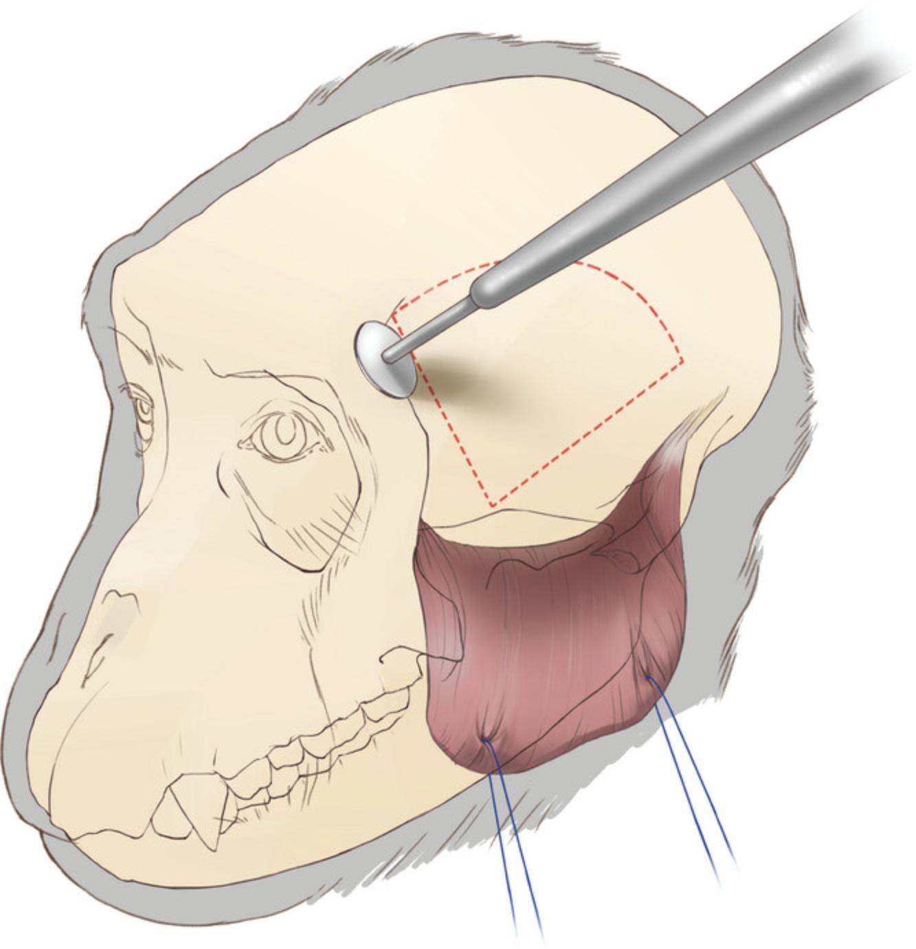
13.Reflect the temporalis muscle toward its ventral insertions, then use traction on the temporalis muscle to maximize access to the temporal bone (Fig. 4).
Craniotomy (bone flap removal)
14.Use a circular cutting wheel (Fig. 4; item #4) at a 45° angle to the surface of the bone. The angle is important since later we replace the bone flap for closure. To prevent dura damage during craniotomy, try not to drill through the full thickness of the skull.
15.Finish the opening by using two periosteal elevators to break the bone flap free from the cranium. Firmly but cautiously insert the elevators along one edge of the craniotomy so as to make contact with the full thickness of the edge of the bone flap without penetrating the dura. Apply pressure to the elevators to carefully lift the bone flap, detaching it gradually from the skull. Move the elevators along the bone flap until at least three sides of the bone flap are detached.
16.While removing the bone flap, carefully detach any dura adhesions by sliding one of the elevators between the flap and the dura.
17.After removing the bone flap, carefully detach any dura adhesions to the skull around the craniotomy margin.
18.Smooth the dorsal and anterior margins of the craniotomy and the bone flap edges using a rongeur.
19.Using a drill bit (item #5), drill four holes on the dorsal edge of the craniotomy which later will be used for suturing the bone flap back into place (Fig. 5). During drilling, use a ‘surgical spoon’ (item #8) between the bone and dura to protect the dura and the cortex. Drill these holes at an angle—exit hole closer to the bone margin than the entry hole—to make it easier to pass a needle through.
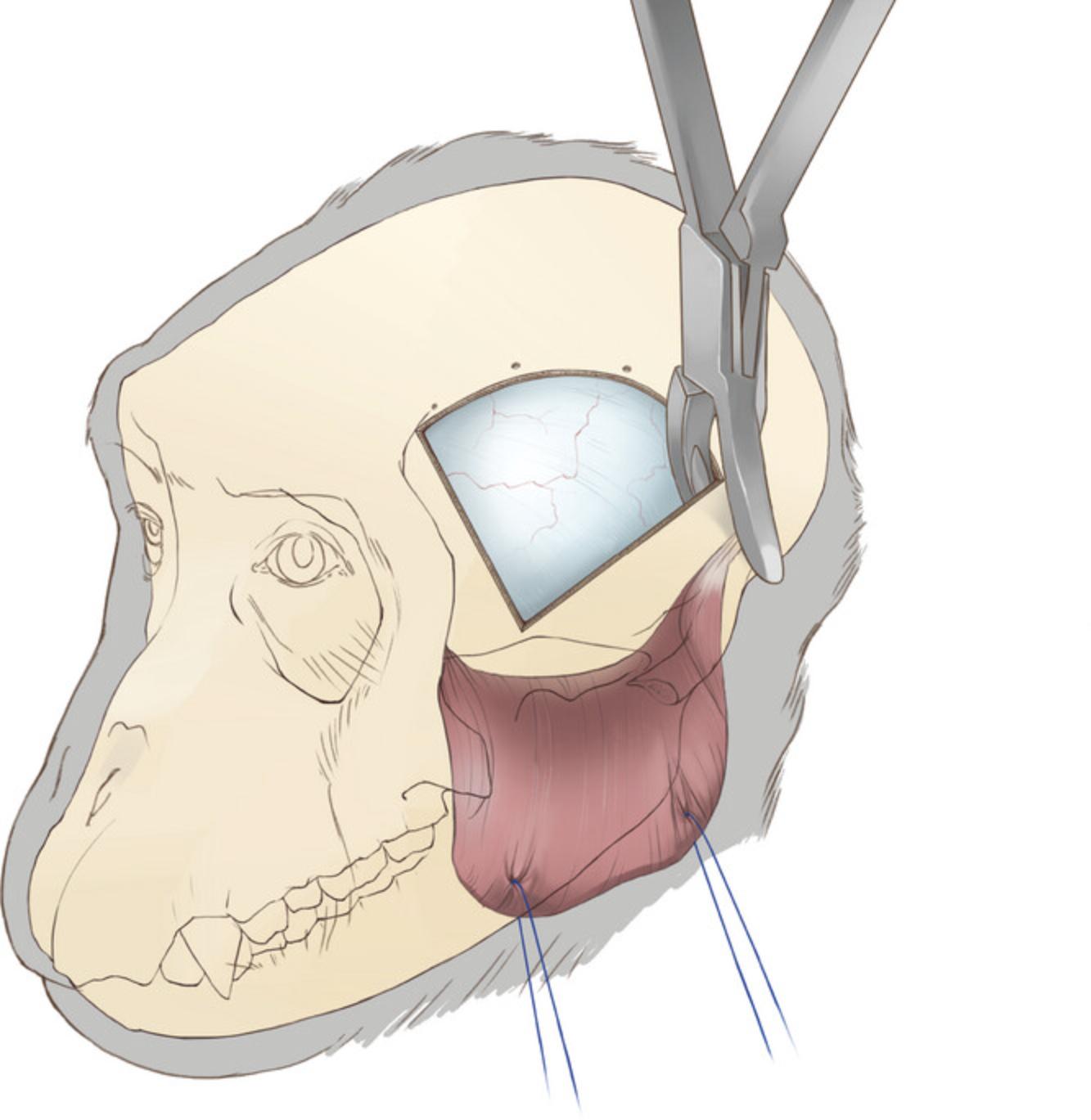
20.Expand the ventral aspect of the craniotomy by rongeuring the temporal and sphenoid bones to the skull base (Fig. 5). Use an elevator to ensure the bone is separated from the dura before rongeuring to avoid tearing the dura or bridging vessels. This expansion of the craniotomy is crucial for accessing the lateral aspect of the inferior temporal cortex.
21.Bone wax can be used to control osteal bleeding around the craniotomy, particularly the ventral side. Use a periosteal elevator and a 5 × 20 mm section of surgical patties (item #3) to press the bone wax into the bone orifices.
Dural opening
A T-shaped incision in the dura provides the best access to the central and anterior IT (Fig. 6).
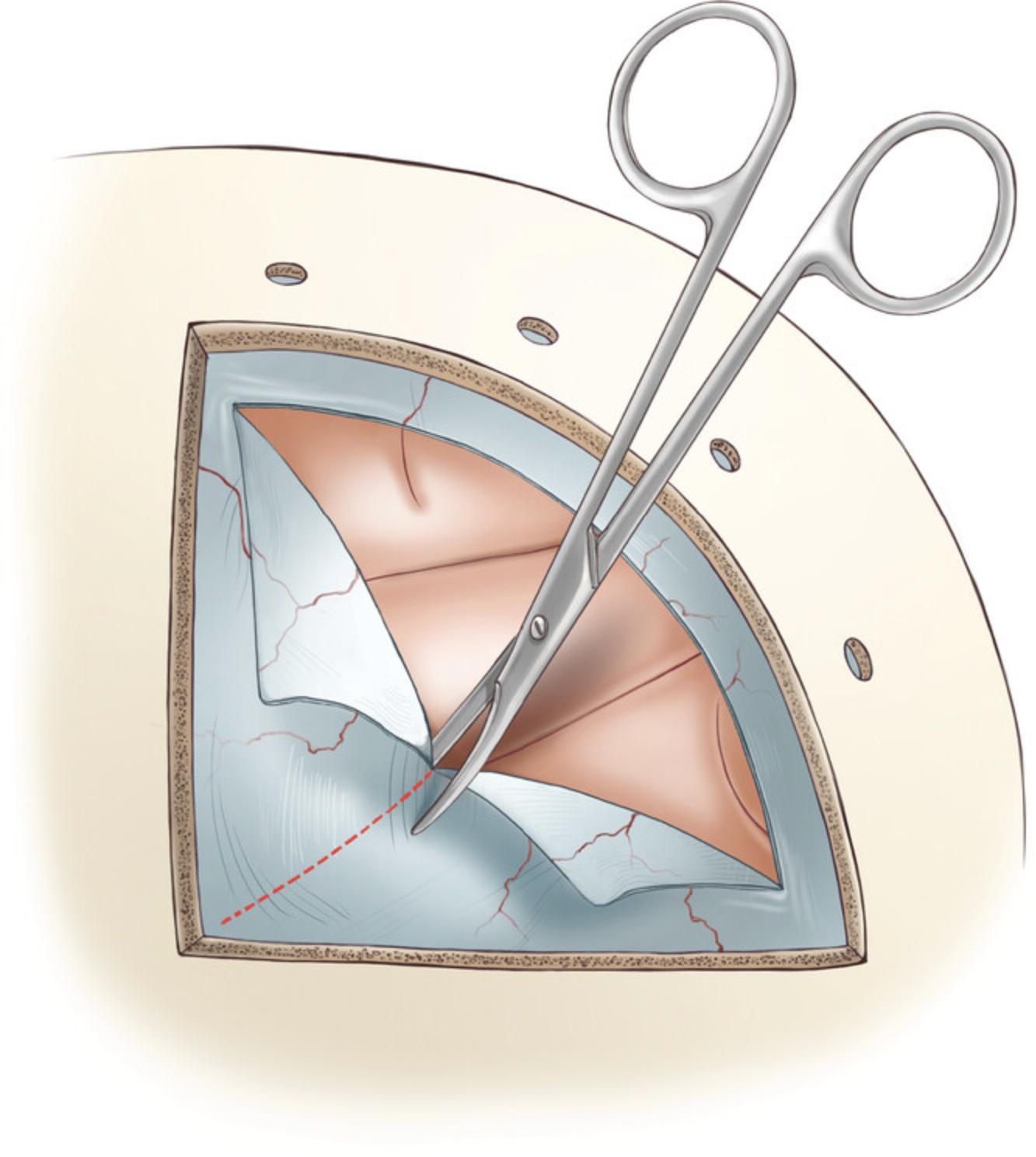
22.Cut the superficial layers of dura using a surgical blade #11.Hold the blade with the sharp edge facing away from the dura. Position the blade parallel to the dura, and make an incision through the superficial layers with the tip of the blade, using a steady and controlled motion.
23.To perform a dural incision, use a Frazier dura hook (∼5″). First, hold the handle of the dura hook with your dominant hand and insert the hook into the partially cut dura. Once the hook is inside the incision, rotate it so that it is perpendicular to the dura surface. Gently pull the dura away from the brain using the hook. To make the first incision, hold a surgical blade #11 parallel to the dura with your other hand, then insert the tip of the blade to fully penetrate the dura. If the dura remained intact until this point, cerebrospinal fluid (CSF) will flow out. It is important to be careful and precise when performing this procedure, to avoid any damage to the cortex.
24.Expand the dura opening with a dorsal curved incision with an approximate 4-mm margin from the edge of the craniotomy. Pull the edge of the opened dura with fine forceps (∼3″) away from the cortex and insert an Iris scissor (∼3″) to cut the dura along the craniotomy margin.
25.Perform a second right-angled dural incision towards the temporal pole reaching the rostral-ventral corner of the craniotomy. Apply tension to the edge of the dura with fine forceps and cut with Iris scissors.
26.Optionally, two braided suture lines (e.g., silk/Vicryl 5-0) attached to small hemostatic forceps can be used to provide retraction.
Virus injection
27.To speed up the virus injection procedure, use an injector array: a novel multi-channel injection device designed to target the ventral surface of the cortex, and facilitate efficient and uniform vector delivery to the cortical regions of the nonhuman primate brain. This array consists of four 2.5-mm 31-gauge needles placed on a 3D printed manifold (Fig. 7). For more details and instructions see Fredericks et al., 2020.

28.After the injection procedure, place sterile transparent film (item #9) on the pial surface and mark the injection site, craniotomy margins, and other anatomical landmarks, then remove the film. This film will be used to pinpoint the injection site in the second surgery to make a dural opening of the appropriate size and location.
Dural closure
29.Before closing the dura, cut and place a piece of artificial dura (item #10) between the dura and cortex to prevent the formation of adhesions prior to the second surgery.
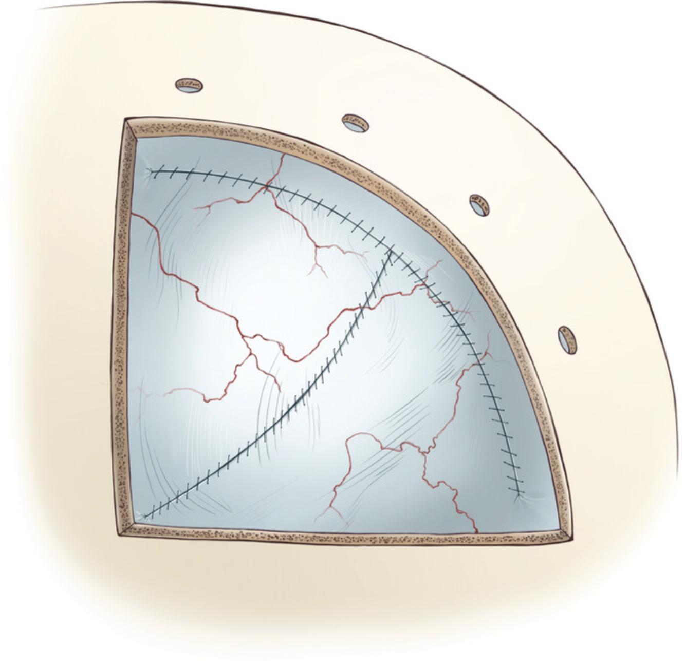
30.Use absorbable braided suture lines (e.g., Vicryl 5-0) for dural closure. First, secure the tips of each dural flap to one another, and then attach the joined region to the dorsal edge of the dura opening with single interrupted sutures.
31.Close the dorsal-ventral incision with a simple continuous suture pattern with 1-2 mm spacing, starting from the rostral-ventral corner of the craniotomy. The dura closure procedure can be completed by closing both sides of the dorsal incision with continuous sutures (Fig. 8).
Bone flap replacement
32.Use non-absorbable sutures for this procedure (e.g., Ethilon 3-0). Pass the suture lines through each of the four holes previously drilled into the skull. Place a grooved surgical spoon (item #8) under the skull while passing the needles through the holes to protect the dura and cortex.
33.Pass the suture lines through all four corresponding holes in the bone flap.
34.Fix the bone flap in place by using square knots. To do this, tie two half knots in opposite directions, allowing gradual tightening. Do not fully tighten a single knot while the rest of them are still loose, as this may misplace the bone flap by pulling it too much to one side. Instead, tighten the knots in parallel by slightly tightening each one in separate steps. After ensuring that the bone flap is securely fastened in place, tie two more half knots to secure the bone flap.
35.Optionally, injectable bone putty can be used to fill the gaps (item #11) and promote osteoinductivity.
Closing
36.Reposition the temporalis muscle to its original location and secure it in place using two or three simple interrupted sutures on the frontal and occipital sides. Choose absorbable suture lines (e.g., Vicryl 3-0) and avoid applying too much tension on the muscle during reattachment.
37.Close the fascia with a simple interrupted or continuous suture pattern with absorbable suture line (Vicryl 3-0).
38.Close the skin with interrupted or continuous horizontal mattress suture patterns with a non-absorbable line (e.g., Ethilon 3-0).
Post-operative care
39.Monitor the animal's heart rate, temperature, and respiration until it regains consciousness. Then transfer the animal to a heated cage in an ICU or return to its home cage. Standard post-operative treatment consists of prophylactic antibiotics (e.g., cefazolin 25 mg/kg IM BID for 3 days) and analgesics (e.g., ketoprofen 1-2 mg/kg IM BID for 3 days followed by ibuprofen 100 mg PO BID for 4 days). If cerebral edema or swelling occurs, mannitol (2 mg/kg IV) and/or dexamethasone (4 mg IM BID) may be administered. Monitor the animal for seizure activity for at least 3 days post-operatively and treat any seizures with diazepam (0.25-1 mg/kg IM) as needed. Moreover, provide supportive care such as softened food, additional fresh fruit, fluid, and electrolyte oral supplements during the post-operative recovery period. The animal routinely resumes post-operative testing 10 to 14 days after surgery based on an uneventful recovery period.
Basic Protocol 2: OPTO-ARRAY IMPLANTATION
The second surgery is performed 4 to 8 weeks after the first surgery. The goal of the second surgery is to confirm virus expression and implant the Opto-Array. The general approach and closing is the same as the first surgery. Drill the bone flap on the same lines as the first surgery if the bone flap has fused with the skull.
Materials
- Everything used in Basic Protocol 1, except injection array and viruses.
- Light source (item #13)
- Light filter (item #13)
- Opto-Array (item #12; for more details see Rajalingham et al., 2021)
- Opto-Array driver and portable computer
- Self-drilling titanium screws (6 mm; item #14)
- Medical-grade polypropylene mesh (item #15)
- Titanium plates (item #16)
- Self-drilling titanium screws (3.5 mm; item #17)
- Artificial dural graft (item #18)
- Self-tapping titanium screws (item #19)
- Self-tapping titanium screws (item #20)
- Dental acrylic
- Adhesive cement system (item #21)
Dural opening
1.After removing the external artificial dura (if used) between the dura and skull, use the transparent film marked in the first surgery to find the injected site.
2.Perform a horizontal dural incision parallel to the skull base at least 10 mm dorsal to the injection site (Fig. 9; follow the procedure explained in Basic Protocol 1; steps 21-22, ‘Dural opening’ section 2.1.5).
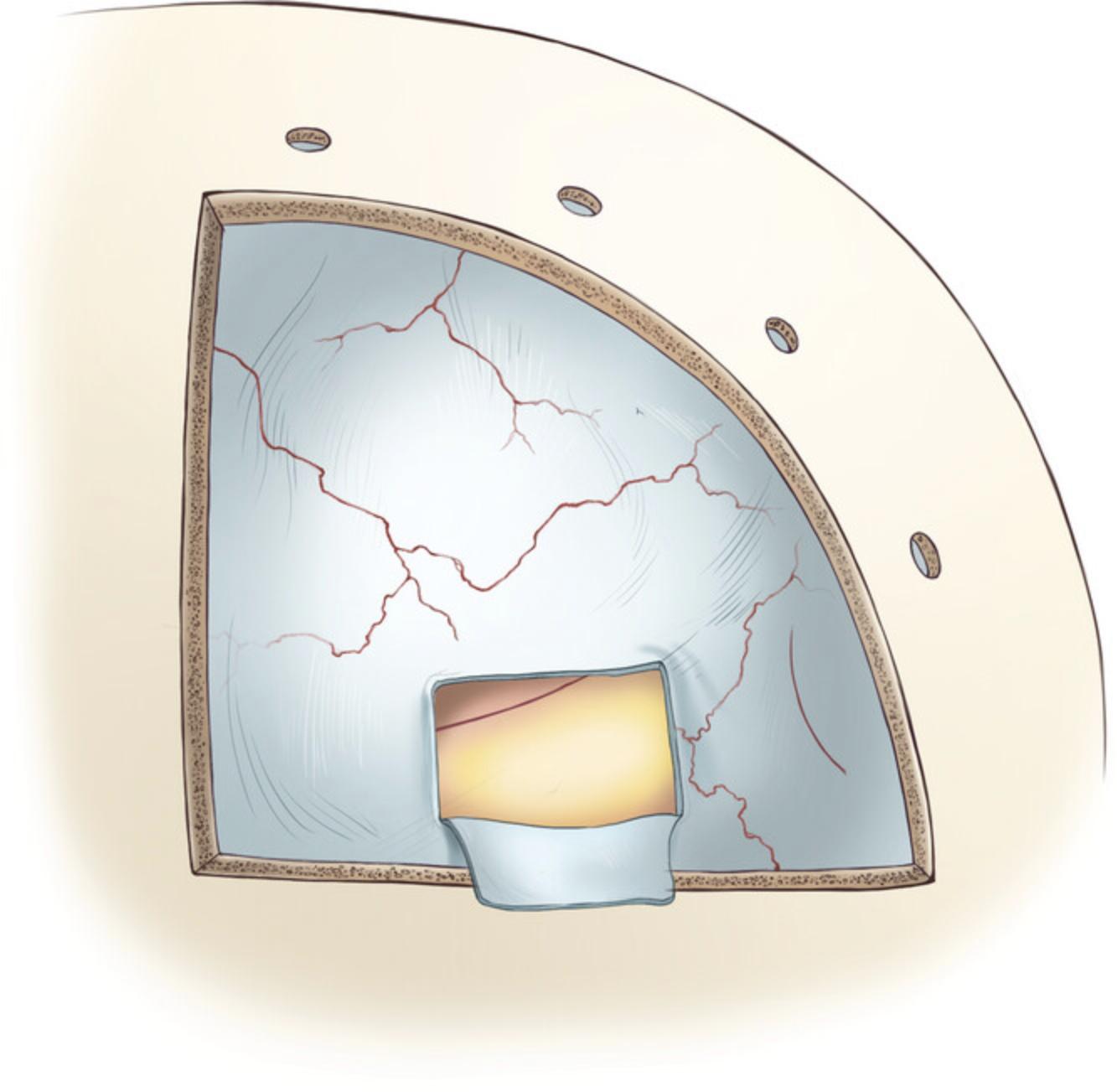
3.Perform two parallel dural incisions extending to the ventral margin of the craniotomy. The distance between the parallel incisions should be 4 mm, which is the distance between the Opto-Array (item #12) holes. Keep in mind that the opening will widen after the incisions are made, so it is best to plan for a slightly smaller opening.
4.After opening the dura, remove the artificial dura placed between the dura and cortex in the first surgery using fine forceps to expose the cortex.
Virus expression verification
5.To confirm expression of the viral payload, check and document the fluorescent signature of the virus. Use a light source and filter (item #13) with wavelengths matching the virus fluorescent protein (for example, 440-460-nm excitation light, 500-nm longpass filter for cells expressing green GFP). Turn off the ambient lights in the operating room and use the light source to illuminate the cortical surface. Then look at the cortical area through the filter, which blocks most of the light reflected from the cortex. The GFP should emit a wavelength that passes through the filter, causing the cortex to appear to be glowing. Capture the evidence of expression by taking a photograph.
Opto-Array implantation
6.Secure the connector pedestal to the skull with two self-drilling titanium screws (6 mm; item #14). The remaining screws to secure the pedestal connector will be placed later in the procedure.
7.Implant the array by suturing the holes located on its four corners to the edges of the dural window that was opened in the previous step (Fig. 10). Surgeon's knots and braided non-absorbable suture material should be used to secure the array in place (5-0 silk).
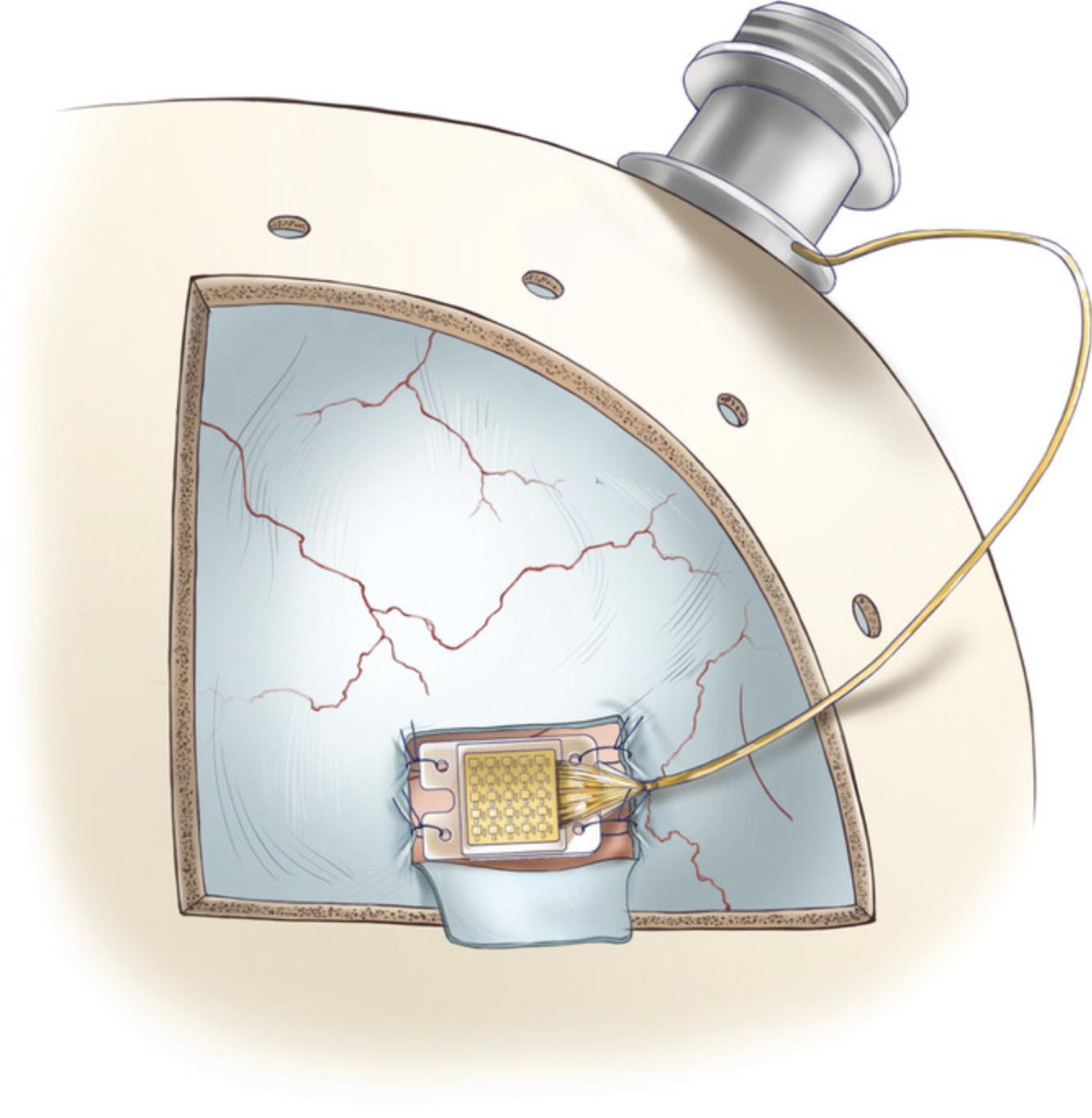
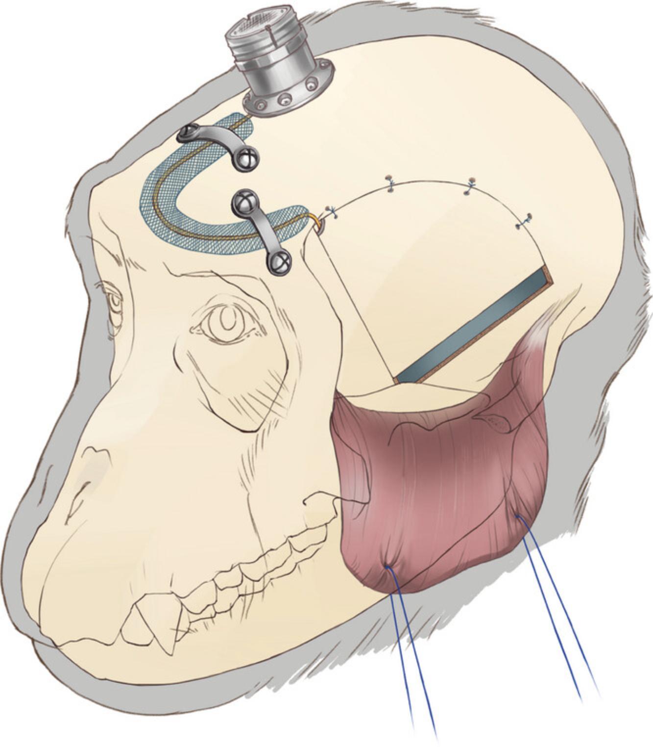
8.The skin around the pedestal implant may gradually recede, exposing the wires. To protect the wires, cover them with a medical-grade polypropylene mesh (item #15) made for hernioplasty surgeries. Secure the wire and the mesh on the skull with titanium plates (item #16) and self-drilling titanium screws (3.5 mm; item #17).
9.Test the Opto-Array to make sure it was not damaged during implantation of the array and wire by connecting it to its driver and associated portable computer, and running a script that flashes each light.
Dural closure
10.Place the dura flap back to cover the Opto-Array, suture the dorsal edge followed by the anterior edge. For dura closure, use braided absorbable sutures (Vicryl 5-0) in a simple interrupted pattern (Fig. 11).
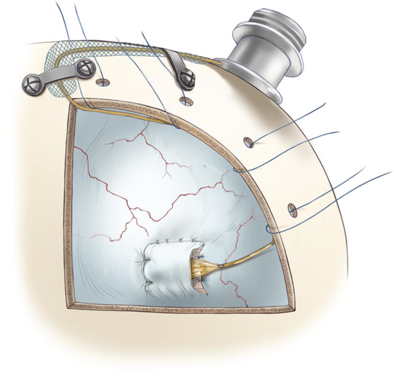
11.After closure, cover the dura with an artificial collagen-based dural graft (item #18) to conceal any gap remaining in the dural opening and to facilitate dural cell growth in the region of the opening.
Pedestal connector implantation
12.After closing the dura and replacing the bone flap (per Basic Protocol 1, steps 32-35), secure the pedestal with self-drilling titanium screws (6 mm; item #14). To avoid damaging the sagittal sinus, avoid placing screws on the sagittal midline (Fig. 12).
Post-operative care
13.Follow the post-operative care outlined in Protocol 1, Step 39.However, enrofloxacin (5 mg/kg PO QD for 7-10 days) is a more suitable choice of antibiotic to protect the tissue around the implanted device from infection.
Basic Protocol 3: BEHAVIORAL TRAINING
Many behavioral experiments are possible using the methods described above. Here, we outline the general task design we use to probe behavioral detection of an optogenetic stimulus and the steps we use to train the animal on this task.
Materials
-
Laboratory macaque monkey with titanium headpost following implantation of Opto-Array
-
Water or fruit juice
-
Behavior chair (item #22)
-
Computerized control system
-
Behavior software (MWorks)
-
Reward delivery system (item #23)
-
Computer monitor
-
Eye tracker (Eyelink 1000, SR Research)
General structure of the behavioral task
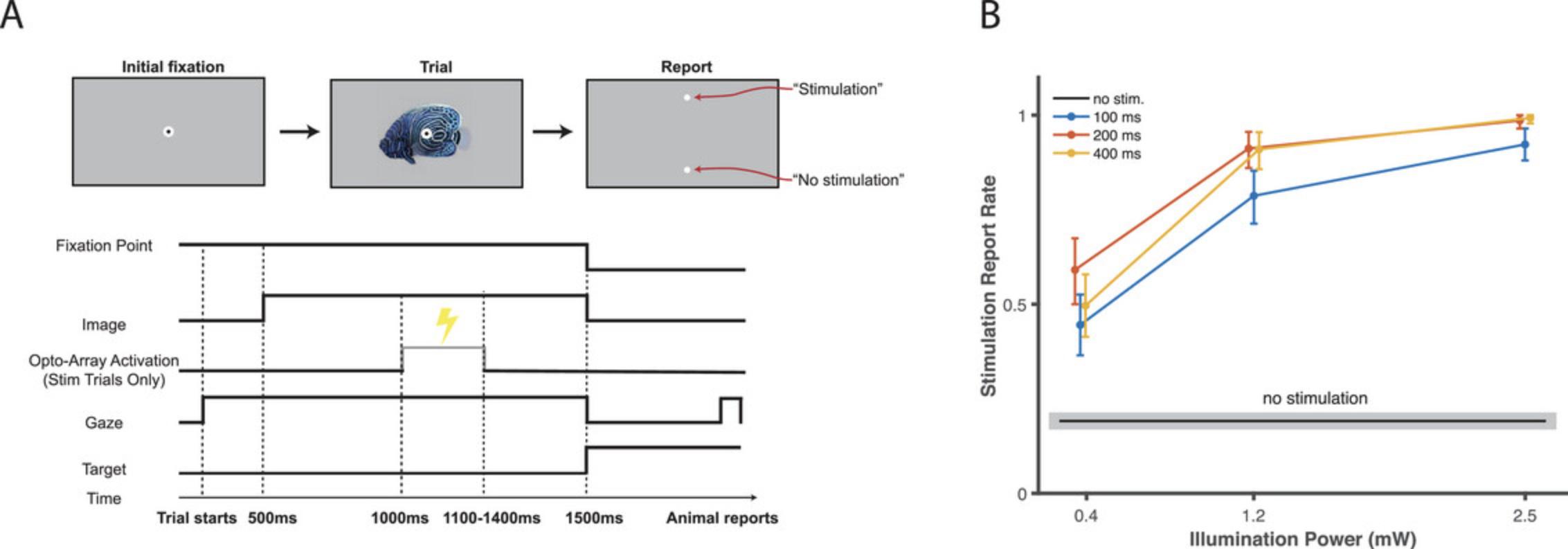
Although specific tasks will differ depending on the experiment, we assume the basics of training non-human primates on complex behavioral tasks are shared and give details on training a macaque monkey to perform the cortical perturbation detection task. The cortical-perturbation-detection (CPD) task is a psychophysical detection task in which the animal is rewarded for correctly identifying whether a given trial contains optogenetic stimulation (Azadi et al., 2022; Azadi et al., 2023; Lafer-Sousa et al., 2023; Rajalingham et al., 2021). Each trial begins with the animal fixating on a central fixation point (black-on-white bullseye, 0.4° outer diameter and 0.2° inner diameter) for 500 ms. Then an image appears on the screen for 1000 ms while the animal must maintain fixation on the central fixation point. In 50% of the trials (randomly selected), 500 ms after the image appears, a cortical stimulation pulse is delivered by illuminating an LED. After the image disappears from the screen, two response targets appear and the animal is trained to fixate on the target that corresponds to the trial condition (“stimulation” or “no-stimulation”).
Before training
Before training on the CPD task, the animal must be trained to enter the primate behavior chair and be motivated by water scheduling. Water scheduling should be performed in accordance with the appropriate Institutional Animal Care and Use Committee (IACUC). Experimental training should take place in a quiet experimental booth equipped with the ability to deliver the animal liquid rewards, track gaze, and display experimental stimuli on a computer screen in front of the animal.
Training step I: Eye tracker calibration
The goal of this step is to gain the ability to automatically reward the animal based on its eye movements. If the animal is naïve to behavioral experiments, it can be difficult to establish a ground-truth eye position because in the uncalibrated system it is not possible to automatically reward the animal for correctly fixating on a fixation point.
1.Start with an eye-tracker calibration derived from another (already trained) animal in the same booth.
2.Begin the eye tracker's calibration sequence. An experimenter should be standing by, observing the eye trace and manually rewarding the animal by giving it a small amount of water/juice through its juice tube (approximately ¼-½ ml) and when the animal appears to fixate on the current calibration point, reward it with water/juice.
Training step II: Fixation training
3.A behavioral task should be prepared that rewards the animal for fixating on a fixation point for a set length of time. In this task, the animal accepts a trial by fixating at a fixation point and must maintain that fixation for a set amount of time. If the animal maintains this fixation, it receives a reward. If it does not, it receives a “time out” in which the fixation point does not appear for a set length of time and it cannot initiate a new trial.
4.Begin training the animal on the fixation task with starting parameters of 200 ms fixation time and 1 s “time out” time.
5.The fixation time should be slowly “walked up” in 50-100 ms increments until the animal is able to fixate for the length of time required by the behavioral experiment. Each increase in fixation time should be done between behavioral sessions, and fixation time should be increased whenever the animal is completing over 85% of the trials it initiates.
6.During fixation training, the volume of reward should be titrated to maximize the number of trials the animal will perform. This should be done by keeping the total amount of water given to the animal per day constant, but reducing the per-trial reward each day by a small amount. The maximum number of trials will vary by subject, but it is reasonable to begin training aiming for 200 trials and finish training aiming for approximately 1000.
Training step III: CPD Task Training
7.Before each day's training, test the Opto-Array. This can be done by manually activating an LED and recording the resulting change in temperature signature. If activating a light causes a change in the onboard temperature sensor, then the light is working. If it fails to elicit one, then the connection should be double-checked or that light may be burnt out and another light should be used.
8.To speed learning, begin by showing only one image to the animal per day and using high light power (5 LEDs, each simultaneously illuminated with 10 to 12 mW). The trial structure is described in the introduction to this section.
9.If the animal develops a choice bias, implement a “correction loop” procedure to the trial structure. A “correction loop” is the addition of a rule to the task that specifies that if the animal makes three wrong choices in a row, every subsequent trial will be delivered as the type opposite to what they have been choosing. The animal is “released” from the loop when they make a correct choice.
10.Once the animal begins detecting cortical stimulations, increase the number of images shown to the animal each day. A doubling procedure (1, 2, 4, 8, 16, etc.) works well. The number of images should be increased whenever the animal's performance is above 85%.
11.Concurrent with increasing image numbers, the power of stimulation should be decreased gradually while maintaining performance above 85%. A reasonable starting power is 5 LEDs at 10 to 12 mW, and a reasonable target power after a month of training is 1 LED at 5 mW.
COMMENTARY
Background Information
The Opto-Array allows us to harness the advantages of optogenetic methods such as cell targeting and stimulation and inhibition of neuronal activity in non-human primates. Using this chronically implantable array of LEDs also facilitates uniform, replicable stimulation and/or inhibition across multiple sessions. Moreover, the chronic nature of this array does not require a cranial chamber, thereby reducing the risk of infection and tissue damage. In Table 1, we list the benefits and limitations of the Opto-Array over other methods. In Table 2, we list some important and novel techniques and surgical approaches presented in this manuscript. Moreover, the surgical approach presented here for accessing IT Cortex can be applied to other procedures such as implanting chronic electrode arrays.
| Acute microelectrodes | Chronically implantable microelectrodes | Optic fiber | Opto-array | |
|---|---|---|---|---|
| Stimulation | yes | yes | yes | yes |
| Inhibition | no | no | yes | yes |
| Cell type targeting | no | no | yes | yes |
| Perturbation of the same site over multiple sessions | no | yes | no | yes |
| Suitable for cortical surface | yes | yes | yes | yes |
| Suitable for deep brain structures | yes | yes | yes | no |
| Necessity of open cranial chambers | yes | no | yes | no |
| Damage caused by penetration | yes | yes | yes | no |
| Commonly used | Presented in this paper | Advantages |
|---|---|---|
| Stereotaxic systems | A low profile head-holder | Better access to the ventral areas since it does not require using earbars; allows rotation of the head during the surgery |
| Cutting through the temporalis muscle | Reflecting temporalis muscle | Less bleeding and tissue damage; dramatically shortens the duration of surgery; increases the field of exposure; faster healing |
| Single needle for virus injection | An injector array | Efficient and uniform vector delivery in parallel; resulting in a shorter procedure |
| Artificial dura or dural grafts for dural closure | Suturing back reflected dura | Assist healing of the dura; isolate the brain; reduce the risk of infection |
| Burrs for craniotomy | Circular cutting wheel | Minimize the gap between the bone flap and craniotomy, allowing bone flap replacement. |
| Titanium or Teflon implants to cover the craniotomy | Bone flap replacement | Minimize the use of foreign bodies; facilitate healing; reduce the chance of complications and infections |
| Self-drilling screws for implanting the pedestal connector | Dental adhesive cement system under the pedestal to fill the gap between the base of the pedestal and the skull | Reduce the chance of local infection and failure by minimizing the empty space under the implant |
| Leaving the wire under the skin without protection | Medical-grade polypropylene mesh to secure the wire | Protecting the wire in case of skin recession |
Surgical access to the ventral and ventrolateral surface cortex, e.g., the IT cortex, in nonhuman primates can be technically challenging, and the lack of explicit and detailed protocols in the literature makes replication of these procedures difficult. We have provided a detailed description of one method for targeting virus and LED arrays to the ventrolateral surface cortex; in doing so, we hope to improve the replicability and reliability of optogenetic experiments in nonhuman primates.
Several elements to the surgical approach described in Protocols 1 and 2 improve upon commonly used methods and are crucial to the success of this procedure (summarized in Table 2). We use a low-profile head-holder instead of a standard stereotaxic system. This allows better access to the ventral areas since it does not require earbars and allows rotation of the head during surgery. To access the skull, instead of cutting through the temporalis muscle, we reflect it. This reduces bleeding and tissue damage, shortens the duration of surgery, and increases the field of exposure, all of which results in a faster healing process. For the craniotomy, we use a circular cutting wheel instead of burrs. This minimizes the gap between the bone flap and craniotomy, allowing bone flap replacement and expediting healing. During virus injections, we use an injector array instead of single-needle injections. This results in efficient and uniform vector delivery, and shorter surgical time. When closing, suturing back reflected dura instead of using artificial dura grafts assists the healing process of the dura and isolates the brain, reducing the risk of infection. To cover the craniotomy, we replace the bone flap instead of using titanium or Teflon implants. This minimizes the introduction of foreign bodies and facilitates healing, thereby reducing the risk of complication or infection. Instead of using self-drilling screws to attach the pedestal connector, we use dental adhesive cement under the pedestal to fill the gap between the base of the pedestal and the skull. This decreases the chance of local infection and failure by minimizing the empty space under the implant. Finally, we use medical-grade polypropylene mesh to secure the Opto-Array wire under the skin. This protects the wire in case of skin recession.
Understanding Results
We measured the behavioral performance of a rhesus monkey (Macaca mulatta) trained to detect cortical stimulation using an Opto-Array implanted on the IT cortex of the left hemisphere. In the first surgery we injected adeno-associated virus 5 (AAV5) expressing excitatory opsin C1V1 under the CaMKIIa promoter. In the second surgery we confirmed virus expression via fluorescent signature and implanted an Opto-Array on the central IT cortex. Following recovery from the second surgery, we trained the animal to behaviorally detect the optogenetic cortical stimulation evoked by illumination of a single LED on the Opto-Array. We used the psychophysical detection task described in Basic Protocol 3. The stimulation intensities were randomly chosen from three stimulation powers (0.4, 1.2, and 2.5 mW) and three stimulation durations (100, 200, and 400 ms). The choice phase was cued by the disappearance of the fixation point and image, after which two visual targets were presented on the vertical midline of the screen (at 5° eccentricity). The animal received a liquid reward for saccading to a response target associated with the trial condition (“stimulation” or “no-stimulation”).
The animal was able to detect the optogenetic impulses across all tested illumination powers and durations (n = 2416 trials; permutation test, p < 0.001 for all comparisons, Benjamini-Hochberg corrected; Fig. 13B). For each stimulation duration, the stimulation was detected at a higher rate when the light intensity was higher (Spearman's correlation between performance (hit rate) and illumination power r = 0.52, 0.60, 0.58, p < 0.001 respectively for 100 ms, 200 ms, and 400 ms duration). To summarize the results and analyze the effect of illumination duration and power, we ran the following linear regression on the data:
Where Power and Duration of illumination are independent variables and HitRate is the animal performance for detecting optogenetic stimulation. The results showed this regression model can significantly explain the performance of the animal (R2 = 0.42, F(3, 2412) = 848, p < 0.001). Moreover, both power and duration of illumination significantly modulate This performance (β0 = 0.20, t(2412) = 18.9, p < 0.001; β1 = 0.22, t(2412) = 19.3, p < 0.001; β2 = 0.02, t(2412) = 13.2, p < 0.001).
These results demonstrate that the surgical procedure and behavioral training steps described in procedures 1-3 create the conditions for eliciting reliable behavioral effects from a range of optogenetic illumination intensities and durations. The similarity of performance across different stimulation durations suggests that illumination longer than 200 ms may produce a “ceiling effect” with respect to the channel kinetics of adaptation for C1V1, the optogenetic channel used here. Notably, to achieve these behavioral effects, the illumination powers used in the present experiment were far below the maximum capacity of the Opto-Array. In this experiment, we used a single LED powered to between 1% and 4% of the maximum individual light capacity of a single LED. Other experimental conditions (for example, a less sensitive behavioral task, or usage of an inhibitory opsin) may require the activation of more LEDs and/or a higher power of activation.
Critical Parameters and Troubleshooting
Every stage of the outlined protocols is crucial. To some extent, the success of the procedure will depend on the surgeon's technical proficiency, so it is important to be well-prepared and to have a clear plan in place before the surgery.
It is a good idea to have backup virus and a primed injection system on hand before commencing protocol 2. If no fluorescence is observed during protocol 2 step 5, the virus is not expressing. In this case, place additional virus injections as outlined in protocol 1, and continue with Opto-Array placement.
It is essential to inspect the Opto-Array before beginning each session in Protocol 3 (step 7). The temperature should be monitored to ensure that each LED is functioning correctly; a slight increase in temperature following activation of an LED indicates proper operation. If the temperature does not rise, the contacts may be dirty and require cleaning with 70% isopropyl alcohol and cotton swabs. If the problem persists, the LED driver or its cables may be faulty and require replacement. Broken or burnt-out LEDs can also cause this problem, but in that case there is no remediation possible.
Time Considerations
Basic Protocol 1: in our experience, the surgery may take between 8 to 10 hr, followed by 4 to 8 weeks for the virus to be expressed.
Basic Protocol 2: the surgery may take between 8 and 10 hr, followed by 3 to 8 weeks for the healing process and starting water control.
Basic Protocol 3: 2 to 4 months
All procedures presented in this manuscript were conducted under an Animal Study Protocol approved by the National Institute of Mental Health Animal Care and Use Committee.
Acknowledgments
The authors thank Erina He from NIH Medical Arts and Emily Lopez for their critical help in preparing the illustrations, and Dr Richard Sanders for comments on the manuscript. This research was supported by the Intramural Research Program of the NIMH ZIAMH002958 (to A.A.).
Author Contributions
R.A. prepared the illustrations and the original manuscript with guidance from M.E. and A.A.; S.B. ran the experiment and collected the behavioral data. S.B. and R.A. analyzed the data and prepared the results. S.B., M.E. and A.A. edited the manuscript; all authors reviewed the manuscript.
Conflict of Interest
The authors declare no conflict of interest.
Open Research
Data Availability Statement
Data available on request from the authors
Supporting Information
| Filename | Description |
|---|---|
| cpz1704-sup-0001-tableS1.docx17.6 KB | Table S1: list of items |
Please note: The publisher is not responsible for the content or functionality of any supporting information supplied by the authors. Any queries (other than missing content) should be directed to the corresponding author for the article.
Literature Cited
- Azadi, R., Bohn, S., Lopez, E., Lafer-Sousa, R., Wang, K., Eldridge, M., & Afraz, A. (2022). Behavioral detection of optogenetic stimulation in inferior temporal cortex depends on the image being viewed. doi: 10.21203/rs.3.rs-1331186/v4
- Azadi, R., Bohn, S., Lopez, E., Lafer-Sousa, R., Wang, K., Eldridge, M. A. G., & Afraz, A. (2023). Image-dependence of the detectability of optogenetic stimulation in macaque inferotemporal cortex. Current Biology: CB , 33, 581–588.e4. doi: 10.1016/j.cub.2022.12.021
- Bernstein, J. G., & Boyden, E. S. (2011). Optogenetic tools for analyzing the neural circuits of behavior. Trends in Cognitive Sciences , 15, 592–600. doi: 10.1016/j.tics.2011.10.003
- Diester, I., Kaufman, M. T., Mogri, M., Pashaie, R., Goo, W., Yizhar, O., … Shenoy, K. V. (2011). An optogenetic toolbox designed for primates. Nature Neuroscience , 14, 387–397. doi: 10.1038/nn.2749
- El-Shamayleh, Y., & Horwitz, G. D. (2019). Primate optogenetics: Progress and prognosis. Proceedings of the National Academy of Sciences of the United States of America , 116, 26195–26203. doi: 10.1073/pnas.1902284116
- Fenno, L., Yizhar, O., & Deisseroth, K. (2011). The development and application of optogenetics. Annual Review of Neuroscience , 34, 389–412. doi: 10.1146/annurev-neuro-061010-113817
- Fredericks, J. M., Dash, K. E., Jaskot, E. M., Bennett, T. W., Lerchner, W., Dold, G., … Eldridge, M. A. G. (2020). Methods for mechanical delivery of viral vectors into rhesus monkey brain. Journal of Neuroscience Methods , 339, 108730. doi: 10.1016/j.jneumeth.2020.108730
- Galvan, A., Stauffer, W. R., Acker, L., El-Shamayleh, Y., Inoue, K.-I., Ohayon, S., & Schmid, M. C. (2017). Nonhuman primate optogenetics: Recent advances and future directions. The Journal of Neuroscience: The Official Journal of the Society for Neuroscience , 37, 10894–10903. doi: 10.1523/JNEUROSCI.1839-17.2017
- Gerits, A., Farivar, R., Rosen, B. R., Wald, L. L., Boyden, E. S., & Vanduffel, W. (2012). Optogenetically induced behavioral and functional network changes in primates. Current biology: CB , 22, 1722–1726. doi: 10.1016/j.cub.2012.07.023
- Gerits, A., & Vanduffel, W. (2013). Optogenetics in primates: A shining future? Trends in Genetics: TIG , 29, 403–411. doi: 10.1016/j.tig.2013.03.004
- Han, X. (2012). Optogenetics in the nonhuman primate. Progress in Brain Research , 196, 215–233. doi: 10.1016/B978-0-444-59426-6.00011-2
- Lafer-Sousa, R., Wang, K., Azadi, R., Lopez, E., Bohn, S., & Afraz, A. (2023). Behavioral detectability of optogenetic stimulation of inferior temporal cortex varies with the size of concurrently viewed objects. Current Research in Neurobiology , 4, 100063. doi: 10.1016/j.crneur.2022.100063
- Mattis, J., Tye, K. M., Ferenczi, E. A., Ramakrishnan, C., O'Shea, D. J., Prakash, R., … Deisseroth, K. (2011). Principles for applying optogenetic tools derived from direct comparative analysis of microbial opsins. Nature Methods , 9, 159–172. doi: 10.1038/nmeth.1808
- Rajalingham, R., Sorenson, M., Azadi, R., Bohn, S., DiCarlo, J. J., & Afraz, A. (2021). Chronically implantable LED arrays for behavioral optogenetics in primates. Nature Methods , 18, 1112–1116. doi: 10.1038/s41592-021-01238-9
- Tremblay, S., Acker, L., Afraz, A., Albaugh, D. L., Amita, H., Andrei, A. R., … Platt, M. L. (2020). An open resource for non-human primate optogenetics. Neuron , 108, 1075–1090.e6. doi: 10.1016/j.neuron.2020.09.027
Citing Literature
Number of times cited according to CrossRef: 3
- Sayuki Takara, Hiroyuki Kida, Takao Inoue, Development of implantable devices for epilepsy: research with cats, dogs, and macaques in biomedical engineering, Advanced Robotics, 10.1080/01691864.2024.2345655, 38 , 14, (983-1007), (2024).
- Elia Shahbazi, Timothy Ma, Martin Pernuš, Walter Scheirer, Arash Afraz, Perceptography unveils the causal contribution of inferior temporal cortex to visual perception, Nature Communications, 10.1038/s41467-024-47356-8, 15 , 1, (2024).
- Arash Afraz, Behavioral optogenetics in nonhuman primates; a psychological perspective, Current Research in Neurobiology, 10.1016/j.crneur.2023.100101, 5 , (100101), (2023).

