MicroStone: Exploring the capabilities of the Artec Micro in scanning stone tools
Armando Falcucci
3D scanning
Artec Micro
Archaeology
Artec Studio Professional
Lithics
Stone Tools
Paleolithic Archaeology
Geometric Morphometrics
GM
Three-dimensional
Bladelet
Disclaimer
The stone tool used to run this example is not an archaeological item but a bladelet resulted from an experimental knapping activity conducted at the Department of Early Prehistory and Quaternary Ecology at the University of Tübingen.
Abstract
In this protocol, I describe how to scan small-sized lithics with the high-precision desktop 3D scanner Artec Micro. This scanner is particularly efficient when it comes to scan small objects with a 3D resolution of up to 0.029 mm and a 3D accuracy of 0.01 mm. However, a few slight modifications to the common workflow are needed to obtain accurate 3D meshes of small stone tools such as bladelets, microblades, microflakes. Overall, this scanner represents an efficient and reliable alternative to scan artifacts that cannot be successfully captured by other laser or structured light scanners, such as the Artec Space Spider. If several hundreds of artifacts need to be scanned, a less time-consuming alternative is represented by Micro-CT scanners, using a protocol specifically adapted to this task (i.e., the StyroStone Protocol). StyroStone Protocol).
Before start
This protocol is optimized to scan small-sized lithics. Therefore, all steps indicated throughout the protocol are related to this particular class of artifacts. The procedure used to scan other artifacts classes might differ slightly. Please, refer to the Artec Micro User Manual for additional information. I recommend watching this video, released by Artec 3D, to have additional tips on the scanning process.
Steps
Part 1 - Object positioning
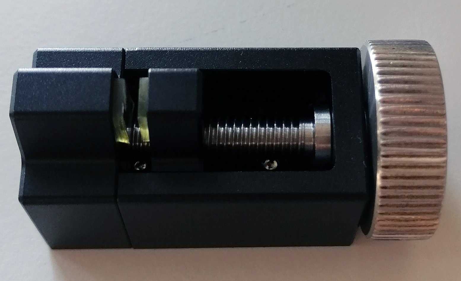
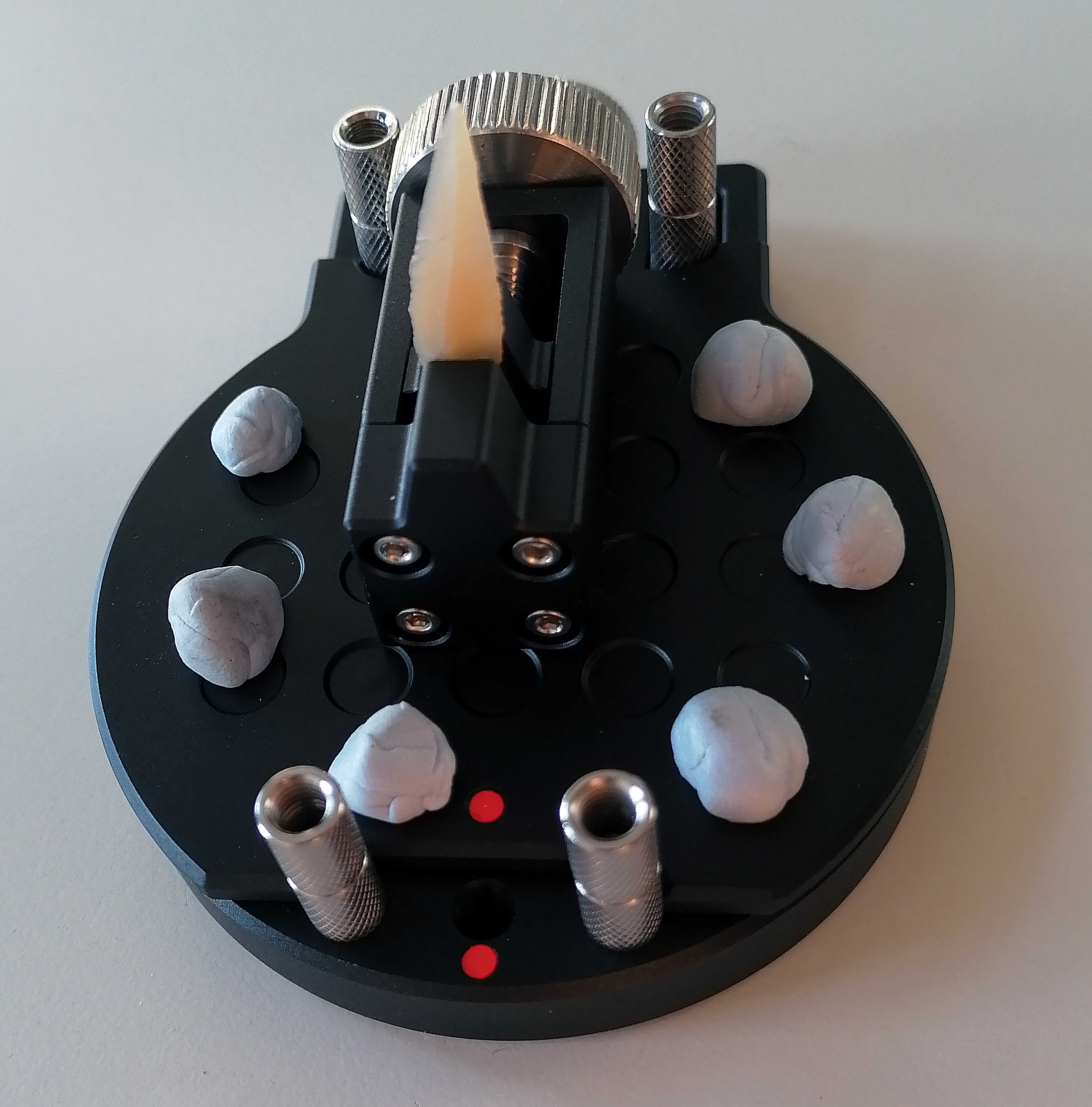
Use the Vise Jig provided by Artec to securely hold the artifact between its jaws (Fig. 1). The Vise Jig can be safely mounted thanks to the magnetic plate (i.e., the Gum Jig ) on the Screw Jig . The object should be stable enough to avoid movements during the scanning process. I recommend placing the object according to its longitudinal axis.
Place additional tracking features on the magnetic plate using an adhesive putty such as the Blu Tack (Fig. 2). This procedure is extremely important when scanning small-sized objects.
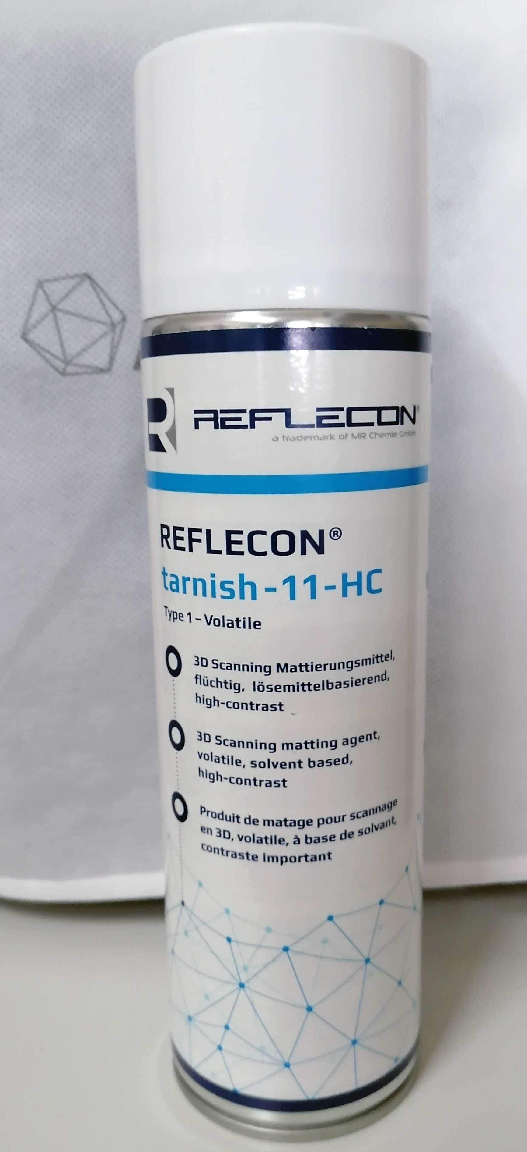
You might need to use a dust anti-glare spray if you are scanning a dark and/or translucent artifact. For instance, the REFLECON®TARNISH 11 is a volatile matting agent for optical 3D laser scanning (Fig. 3). Please, notice that Artec recommends to use an air brush to avoid the formation of unwanted features on the object's surface.
Part 2 - Scan in Artec Studio 16
Boot the computer and the scanner.
Open Artec Studio 16 Software.
The camera view on the top left side (Fig. 6) will show the artifact mounted on the Vise Jig . If needed, slide it to roughly center the object to the field of view using the red cross as reference. If the object is not entirely visible, remove one or more spacers until it is completely visible.
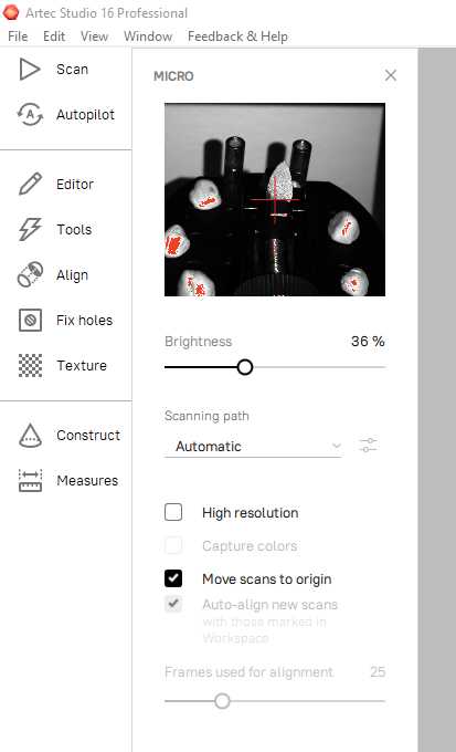
Adjust the brightness to make the object more visible in the preview while avoiding overexposure of the artifact. Overexposed areas are highlighted in red (Fig. 6). The value should be thus adjusted to minimize the red dots on the artifact.
Select the S canning path (Fig. 6) according to the complexity of the artifact. I recommend using the Automatic path, as this setting will automatically calculate the number of frames needed to capture the complexity of the artifact.
Safety note: If the artifact cannot be safely secured on the Vise Jig , select the path Rotation only . In this case, the turntable movement is limited to a fixed number of horizontal rotations.
Select Move scans to origin (Fig. 6).
Extra: If you want to capture the object's texture, select also High Resolution and then Capture colors .
Finally press Scan.
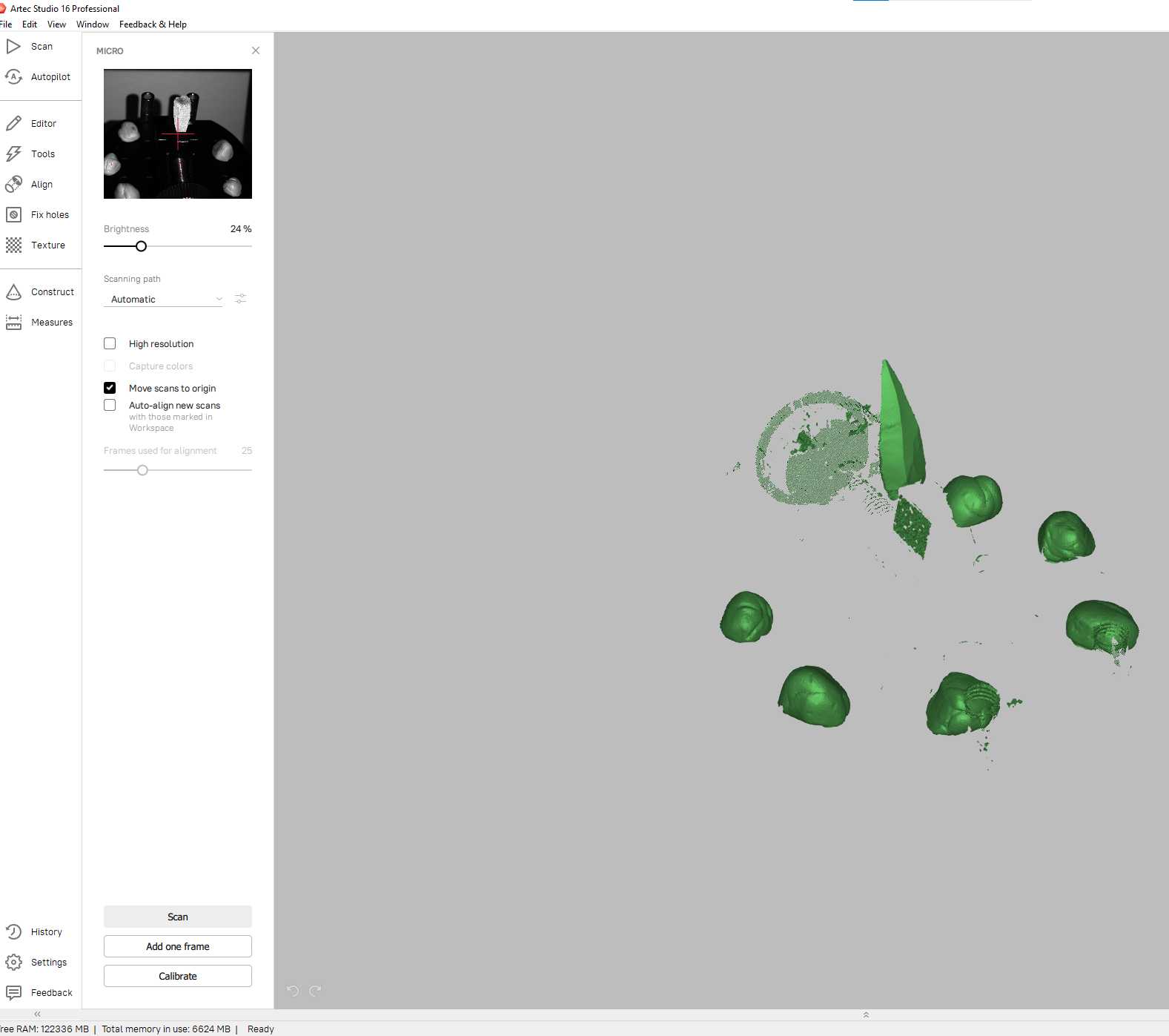
Once the first scan is complete, rotate the artifact, securing it again on the Vise Jig, and start a new scan using the same parameters listed above. Unclick the option Auto-align new scans before pressing Scan (Fig. 7).
Two scans should be enough to capture small objects. If needed, though, run a third and/or fourth scan changing views (e.g., orientating the object according to its transversal axis). This might be needed when artifacts have marked plunging distal terminations.
Part 3 - Processing the scans
After completing the second scan, go to Tools and run a Global registration for each scan separately , by selecting one scan at a time. Key frame ratio should be set to 1 and Search features within, mm to 0.1 (Fig. 8).
Note: This step is highly recommended when scanning small-sized objects, while you may not need to run a global registration for each scan separately when bigger artifacts are scanned. In this case you can simply skip steps 14 and 18.

Go to the Editor panel and select Eraser . Select one scan at a time and erase all scanner's jigs and adhesive putty, leaving only the artifact. The best way to do so is to use the Lasso function (Ctrl + left-click) to first select the whole artifact. Then, select Inverse and Erase (Fig. 9).

Select both scans and go to the Align panel. The left panel will list all scans selected (in this case two). The blue and green dots indicate with scan is movable (i.e., green dot) and which is instead fixed (i.e., blue dot). Rotate the green scan to match the orientation of the other (Fig. 10). To make rotations more effective, double-click on the green object. In this way, the pivot point (displayed as a pink dot) is set on the movable object.

Useful commands during the alignment process:
- Ctrl + left-click of the mouse: Rotate and move the object along its axis;
- Ctrl + click on scroll: Move the object along the x and y axes;
- Ctrl + scroll up and down: Move the object along the z axis.
Select three to four roughly correspondent points on both scans (Fig. 10) and press Align . If the alignment was successful, press Apply to save and exit the alignment process.
Go to Tools again and lock the registrations of each scan before moving to the next steps. This can be done either by clicking on the lock symbol on the right panel or right-clicking on each scan and selecting Lock registration (Fig. 11).

Run a new Global registration using the same parameters listed in Step 14. Note that being the scans locked, this process will result only in a Fine registration process. Nevertheless, this step is recommended to increase the accuracy of the alignment.
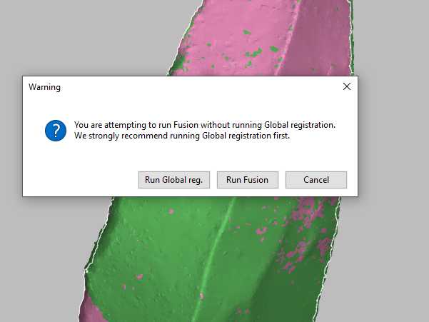
Once you click on Apply , a warning message will appear. Select Run Fusion to proceed (Fig. 13). The software will then create a 3D mesh of the aligned scans.
Part 4 - Postprocessing phase
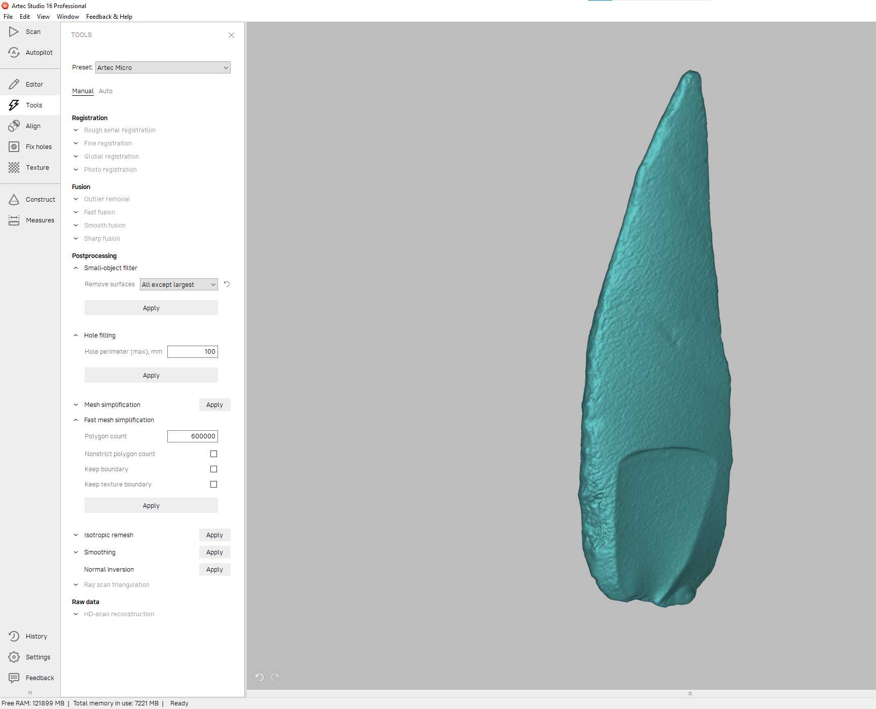
Run the Small-object filter with the option All except largest .
Run Hole filling selecting the Hole perimeter (max), mm at e.g. 100.
Finally, run the Fast mesh simplification . In this example, I used 600,000 polygons (Fig. 14). There is not an ideal number of polygons to be used. Experiment with different values and visually assess how the quality of the mesh is affected, trying to keep all important features unaltered.
If the color function was enabled (see Step 11), move to the Texture panel and select the scans from which you want to get the texture information. Select the resolution preferred and press Apply . Once the texture is applied, the software allows to modify several visual parameters such as saturation, brightness, and hue.
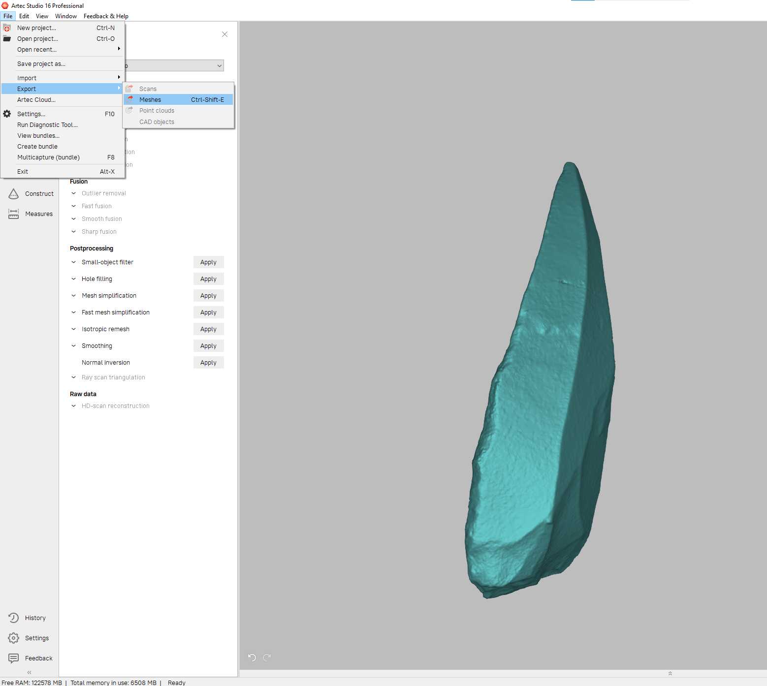
Save the Artec project going to File and selecting Save project as .
Final result
Here you can download the 3D model of the bladelet used in this example. Notice how the retouch, bulbar scar, and the internal fracture on the distal portion of the artifact were successfully captured.


