Full Assessment of Lung Mechanics Using Computer-Controlled, Forced Oscillation Technique
Roldan Medina De Guia, Roldan Medina De Guia, Vaclav Zatecka, Vaclav Zatecka, Jan Rozman, Jan Rozman, Jan Prochazka, Jan Prochazka, Radislav Sedlacek, Radislav Sedlacek
Abstract
The forced oscillation technique (FOT) is a powerful and accurate method to quantify the mechanical properties of the airways and tissues of the respiratory system. Here we provide a detailed protocol for the measurement of mouse respiratory mechanical parameters. We present a procedure for mouse endotracheal intubation using a handcrafted intubation platform and confirmation module. The FlexiVentFX™ system (Scireq Inc.) is utilized for the thorough assessment of lung function with the FlexiWare™ software serving as a unit for the planning, experimentation, and analysis. The protocol has been standardized and adapted for use by our center for lung-function phenotyping of mouse models generated for the International Mouse Phenotyping Consortium (IMPC). The simplified steps, technical considerations, and integrated hardware-software demonstration make this protocol adaptable and implementable for researchers interested in using FOT for lung-function evaluation. © 2022 The Authors. Current Protocols published by Wiley Periodicals LLC.
Support Protocol 1 : Assembly of the FlexiVentFX™ system for measurements
Support Protocol 2 : FlexiWare database management
Support Protocol 3 : A guide for the construction of intubation platform and confirmation module
Basic Protocol 1 : Mouse endotracheal intubation
Basic Protocol 2 : Assessment of mouse basal lung function
INTRODUCTION
Forced oscillation technique (FOT) is a powerful and accurate method to quantify the mechanical properties of the airways and tissues of the respiratory system. It is an essential technique in conditions where a hospital patient has to be ventilated with the aid of mechanical ventilation. The artificial ventilators, which facilitate the patient's respiration, monitor lung mechanics in hospitals and have become particularly relevant during the COVID-19 pandemic. FOT has been adapted for the study of lung function in animal models of pulmonary dysfunction. Here, we present basic and support protocols to enable one to carry out computer-controlled, unchallenged mouse lung function measurements using the FlexiVentFX™ system. The integrated platform of FlexiVentFX™ combines animal ventilation with measurements of respiratory mechanics. Parameters that can be measured include inspiratory capacity, respiratory system resistance and compliance, and intrinsic elastic properties, among others. We describe in detail the support protocols for the assembly of the FlexiVentFX™ system and software management. The basic protocols cover mouse endotracheal intubation and assessment of mouse lung function without a challenge. This compilation of support and basic protocols is designed to help even newcomers in the field to perform lung-function measurements. Figure 1 depicts the protocol workflow.
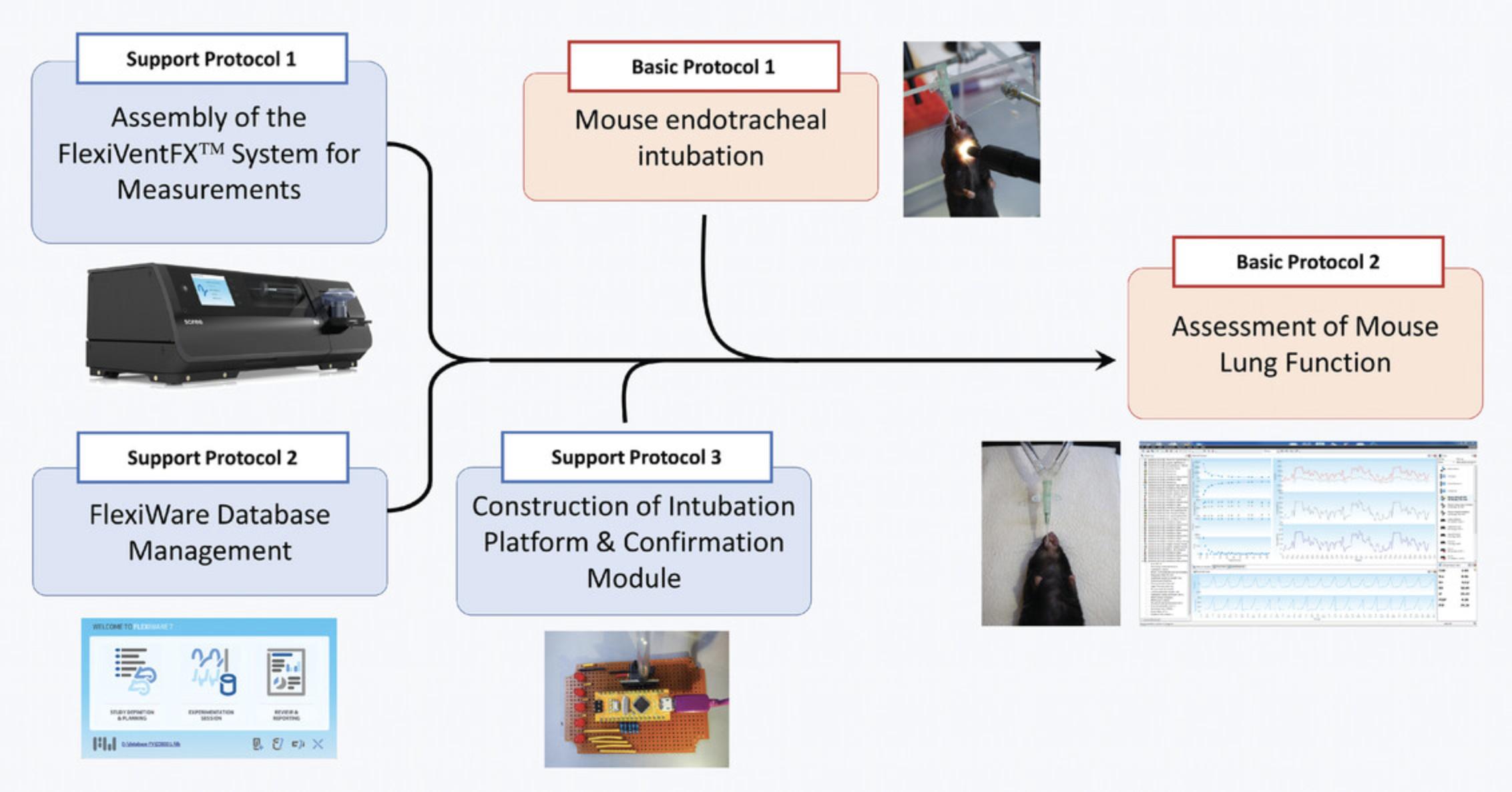
Support Protocol 1 familiarizes the user with the FlexiVentFX™ system and its assembly for unchallenged, mouse lung-function measurements. Illustrations and annotations are provided to make it easier for novice users. As the FlexiVentFX™ system is computer-controlled, acquaintance in advance with Support Protocol 2 is likewise recommended. Support Protocol 3 presents a guide on how to construct a handcrafted intubation platform and breathing confirmation module, which will be needed in the basic protocols. Basic Protocol 1 presents the mouse endotracheal intubation procedure that we standardized in our laboratory. Images and videos of homemade materials and equipment are mentioned so that they can be adopted by other laboratories. Mastery of endotracheal intubation is essential for successful and reproducible measurements. Basic Protocol 2 presents the bulk of the procedure for the assessment of mouse lung function under basal conditions. We provide detailed steps with annotations, figures, and videos covering setup, calibrations, perturbations, troubleshooting, and measurements.
CAUTION : Only gases are allowed to circulate in the system. Introduction of other substances like aerosols may damage the piston of the module. Never attempt to open the base unit while the instrument is running. Ensure proper ventilation and control of possibly harmful substances introduced in the system, to protect the experimenter.
Support Protocol 1: ASSEMBLY OF THE FlexiVentFX™ SYSTEM FOR MEASUREMENTS
The FlexiVentFX™ system is a modular system where different modules are connected to the main chassis (Fig. 2A–C), which handles all communication with the attached computer.
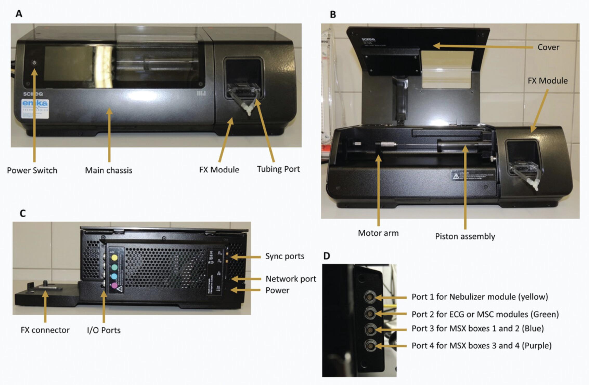
For the different types of measurements, different combinations of modules are necessary. Except for the FX modules, all modules are connected with the I/O ports on the main chassis. They have to be attached to the right I/O port to function properly. For this purpose, the I/O ports and the plates attached to the cables of the modules have been color-coded with a little colored label (Fig. 2C and D).
For all (dis-)assembly procedures, the system needs to be switched off with the power switch on the main chassis (Fig. 2A). Always check that the system is off (display not lit up) before removing any module or cable.
Materials
- FlexiVentFX™ Base Unit and Module (Scireq Inc.):
- FlexiVentFX™ main chassis
- FlexiVentFX™ module
- Tubing ports
- Tubing FX1 module
- Tubing FX2 module
- Y-connector FX1 module
- Y-connector FX2 module
1.Prepare the components of the system needed for the desired measurement.
2.Change the FX module.
- Check that the machine is off and open the cover.
If machine is not off, switch it off. The power button is located on the main chassis (Fig.2A).
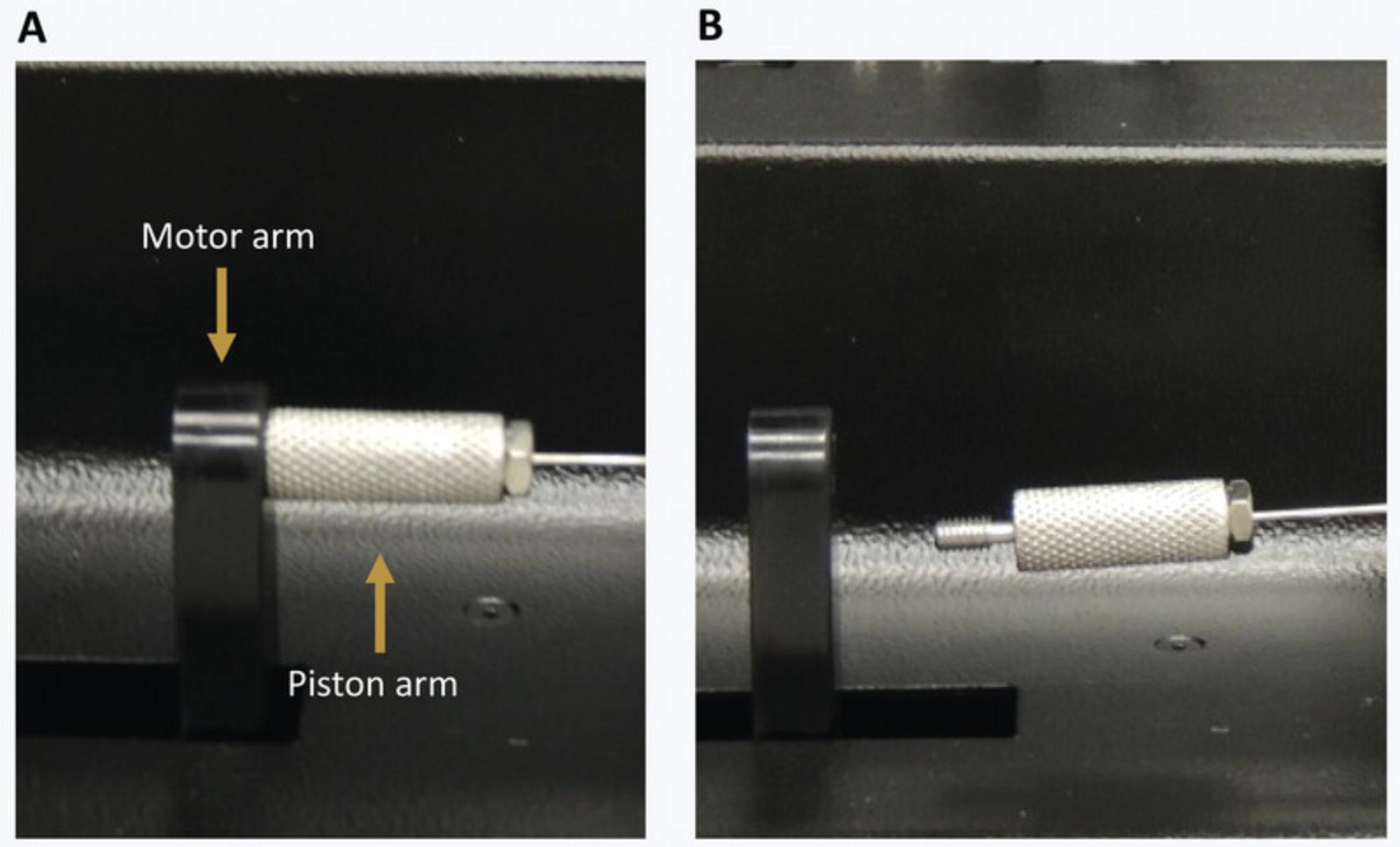
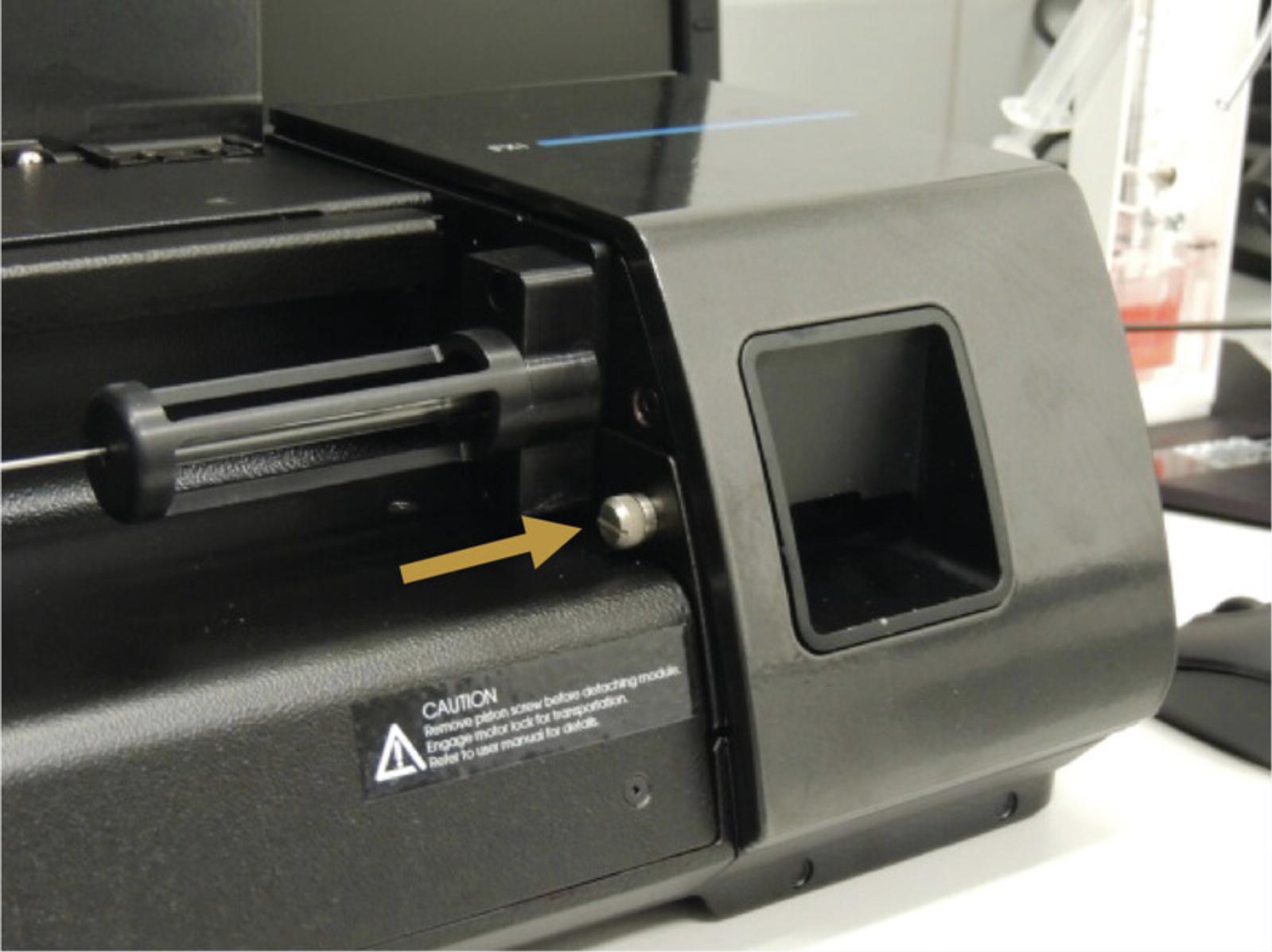
- Unscrew the piston arm from the motor arm (Fig.3A).
The motor arm can be moved without risk of damaging the machine. It will recalibrate its position at start-up.
-
Unscrew the FX module from the FlexiVentFX™ chassis (Fig.4A).
-
Remove the FX module.
Remove the FX module by lifting it upwards. Note that it can only be removed by lifting upwards, as there is a connector on the bottom of the FX modules (Fig.2C).
- Remove the protective tube from the FX module to install.
Remove the protective tube and the bubble wrap.
- Place the protective tube on the FX module to store away.
Place the bubble wrap on the broad part of the piston arm and put on the protective tube.
- Install the FX module.
Insert the FX module on the main chassis by moving it into place vertically. The connector is located at the bottom.
-
Screw the module to the main chassis (Fig.5).
-
Screw the piston arm to the motor arm (Fig.4).
-
Close the cover of the main chassis.
3.Install the tubing port.
- Slide the mounts into the slot on the FX module with the plastic attachment's O-ring facing towards the machine and the metal lever up.
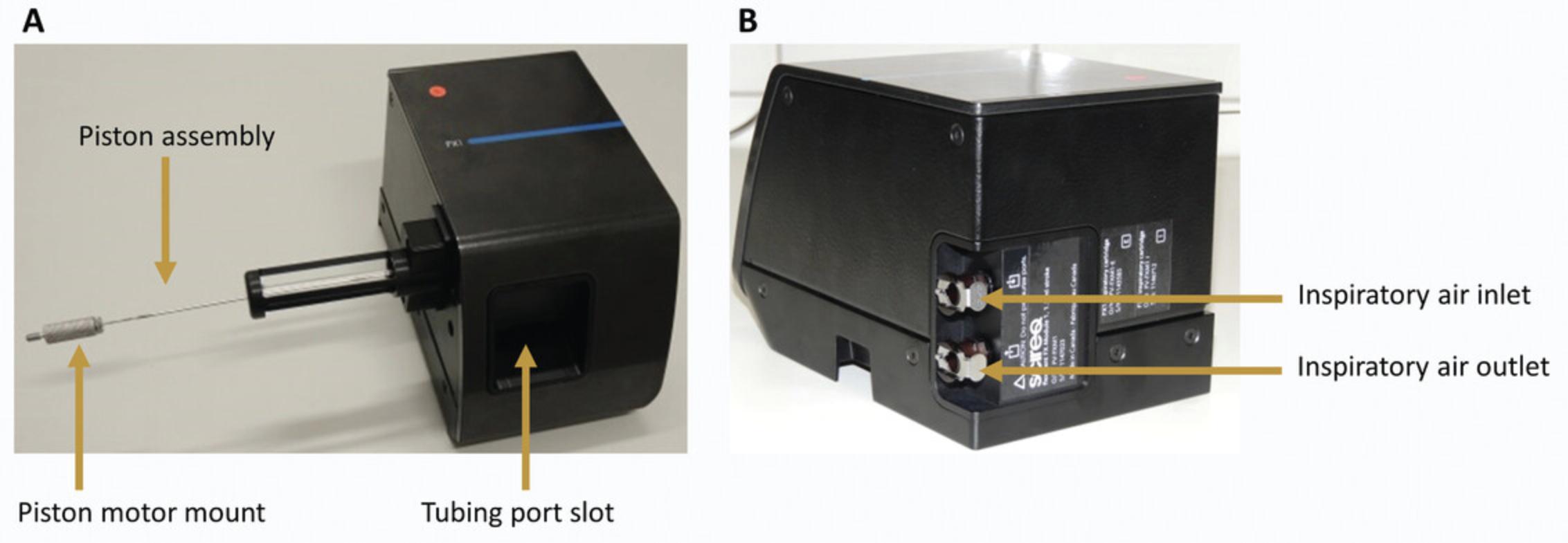
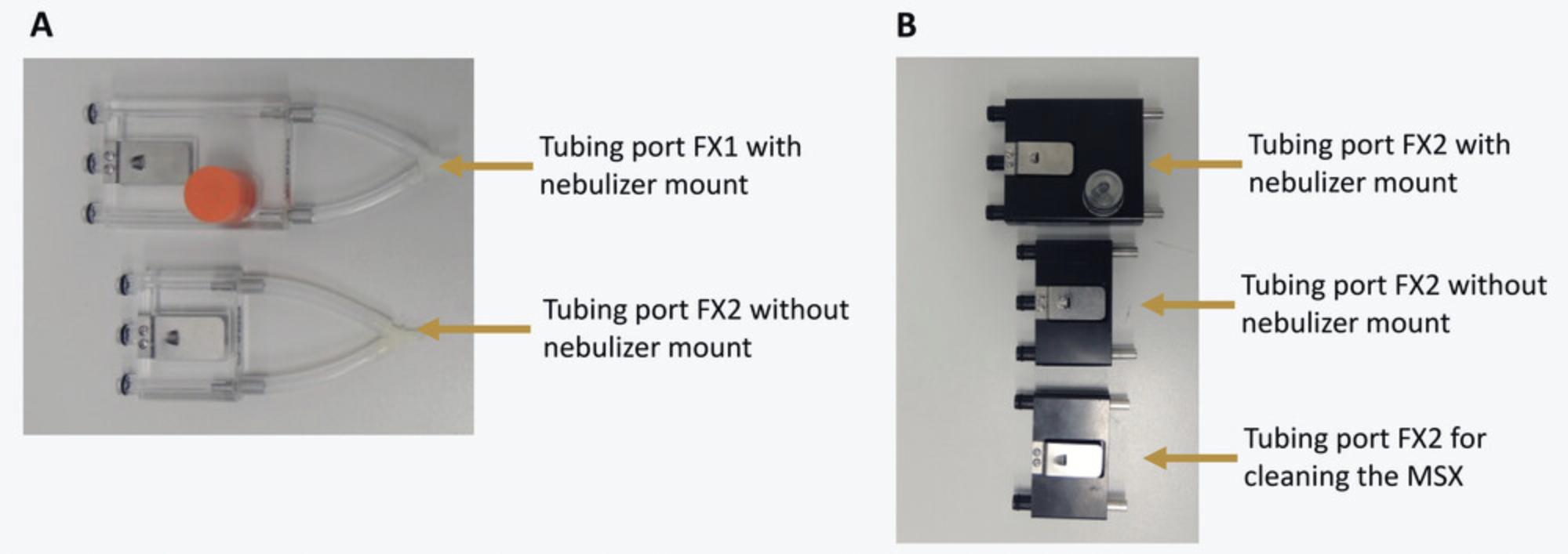
The FX1 modules use tubing ports made of transparent plastic. Two tubing ports are available, with and without a nebulizer mount (Fig.6A). If no pharmacological challenge is needed, select the one without a mount; otherwise use the one with the nebulizer mount.
The FX2 modules use tubing ports made of black plastic. Three tubing ports are available: two for measurement, with or without nebulizer mount, and one for the cleaning of the MSX system (Fig.6B). The latter only has two plastic attachments with O-rings and cannot be used for measurements, as it does not connect to the pressure transducer. For this protocol, you will need the tubing ports without nebulizer mount.
- Connect the tubing assembly if necessary.
Usually the tubing remains attached to the tubing port. If this is not the case, put two pieces of tubing on the metal tubes of the tubing port.
For measurements with single animal: Connect the tubing on the other end to the Y-shaped connector (Fig.6A).
Support Protocol 2: FLEXIWARE DATABASE MANAGEMENT
FLEXIWARE is the software used for measurements with the FlexiVentFX™ systems. It uses a database to store all data that were generated during the measurements.
Due to technical restrictions, the database cannot be bigger than 1.5 GB. With bigger databases, the integrity of the data could be compromised.
This protocol describes how to create new databases and archive old databases so that no data get lost. To easily trace back data, a strict naming convention is recommended for the databases—no other names should be used at any time.
Materials
- FlexiVentFX™ System (Scireq Inc.)
- FlexiWare software (Scireq Inc.) installed on a computer
Steps for the creation of a new database and archiving of the old database
1.Copy the current database to a safe location for backup.
2.Copy the blank database to D:\Flexivent_DB.
3.Rename the copied blank database.
4.Open the FlexiWare software and the database management module.

5.Change the database to the newly created database.
6.Close the system setting window by clicking OK, and restart the software.
Support Protocol 3: A GUIDE FOR THE CONSTRUCTION OF INTUBATION PLATFORM AND CONFIRMATION MODULE
This support protocol describes how to construct the materials made in-house that are presented in the basic protocols. These include the intubation platform and confirmation module for Basic Protocol 1.One should be able to construct the platform and module provided that all the materials below are available. We suggest seeking the help of your institution's electronics and engineering department, as the majority of the materials are available from their workshops, and a basic understanding of circuit building is necessary.
Materials
- For the construction of the intubation platform :
- Polystyrene plexiglas, 200 × 485 × 4 (Gutta, 4003412026749)
- Plexiglas sheet cutter (Fruugo, 73641867-147939002)
- Drill and drill bits (FTM, Inc., BG4650A)
- Super glue (Bison Germany, 80273)
- 3, M8 × 200 mm Head bolts/screws with nuts and washers (TIMco, 08200CB)
- 2, Bolt set with spring washers (Schwer Fittings GmbH, SAE-SET-M8 × 30)
- 25-cm Nylon string (Ibanez, ICLS6NT)
- Waterproof plastic electronic box (100 × 68 × 50 mm; Digital Zakka, 00884322)
- For the construction of intubation confirmation module :
- Circuit board (90 × 150 mm) (Techfun.sk, DPS7920)
- Soldering iron (Powerplus, POWX1382)
- Solder (Pecka Modeler, 5601-199)
- Airspeed sensor Mpxv7002 dp with air hose (Fruugo, 80046867-165799705)
- Arduino Nano V2.0 or higher (Arduino, dratek.cz 1449953245)
- 5 Metallic resistors (100 Ohm, 1% Tolerance) (GYM/CYM, MF0207101FTB)
- 5 LEDs (5 mm, 25 mA) (LED Technology, L07R5000Q1)
- MicroUSB-USB 2.0 0.5 m cable (hb-digital.de, AQ, 5398-001)
- AC EURO Adapter 220V to USB (500 mA) (Joyetech, BEK-QC-001)
- Wires (The Pi Hut, 103745)
A. Steps for the construction of intubation platform
1.Procure all the materials listed in the materials list above.
2.Divide the plexiglas into pieces as needed.
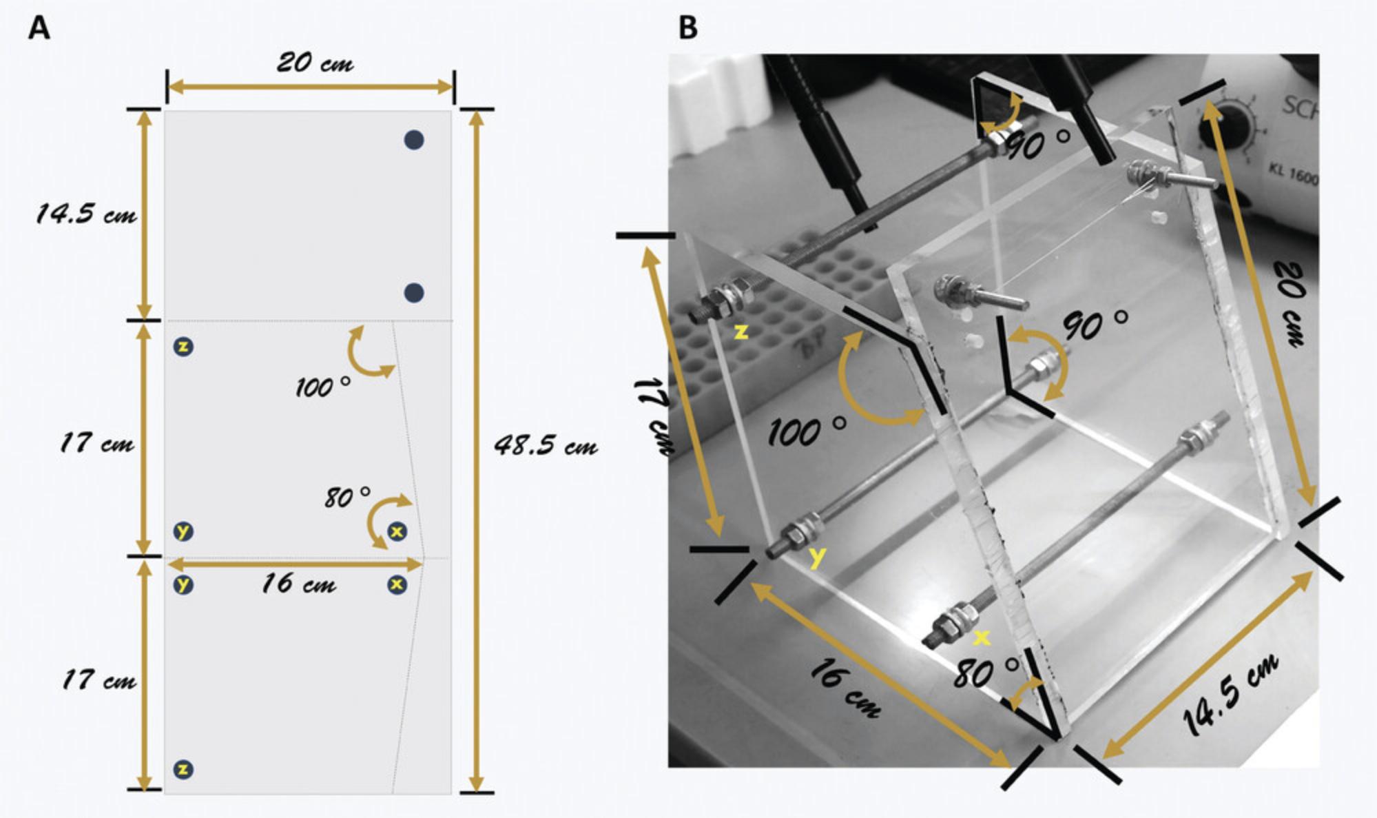
- Mark the plexiglas as shown in Figure8A.
The broken lines in Figure8Arepresent where to cut, while the circles indicate where to drill holes.
- Cut the plexiglas into pieces using a cutter.
There are two identical trapezoidal pieces and one rectangular piece. The inclination in the trapezoidal pieces will provide support to the body of the animal during intubation.
3.Bore holes into the plexiglas where the bolts will be inserted.
4.Assemble the intubation platform.
-
Use Figure8Bas a guide during assembly.
-
Fix the two, smaller, 30-mm bolts and washers into the holes of the rectangular piece.
-
Put two hexagonal nuts into the middle of each of the three, longer, 200-mm bolts.
-
Insert the 200-mm bolts into the holes of each of the trapezoidal pieces.
The holes are lettered x, y, and z to indicate connections of the two pieces.
-
Place washers and nuts to keep the plexiglas fastened.
-
Place the rectangular front piece in between the two trapezoidal side pieces.
Holding the trapezoidal pieces upright (16-cm side at the bottom), slide the pieces to the side, creating a space for the rectangular piece. Use super glue to stick the rectangular front piece to the trapezoidal side pieces.
-
Adjust the washers and nuts to secure the frame of the platform.
5.Tie the nylon string across the two bolts of the rectangular front frame.
B. Steps for the construction of intubation confirmation module
6.Gather all the materials needed as listed in the materials list above.
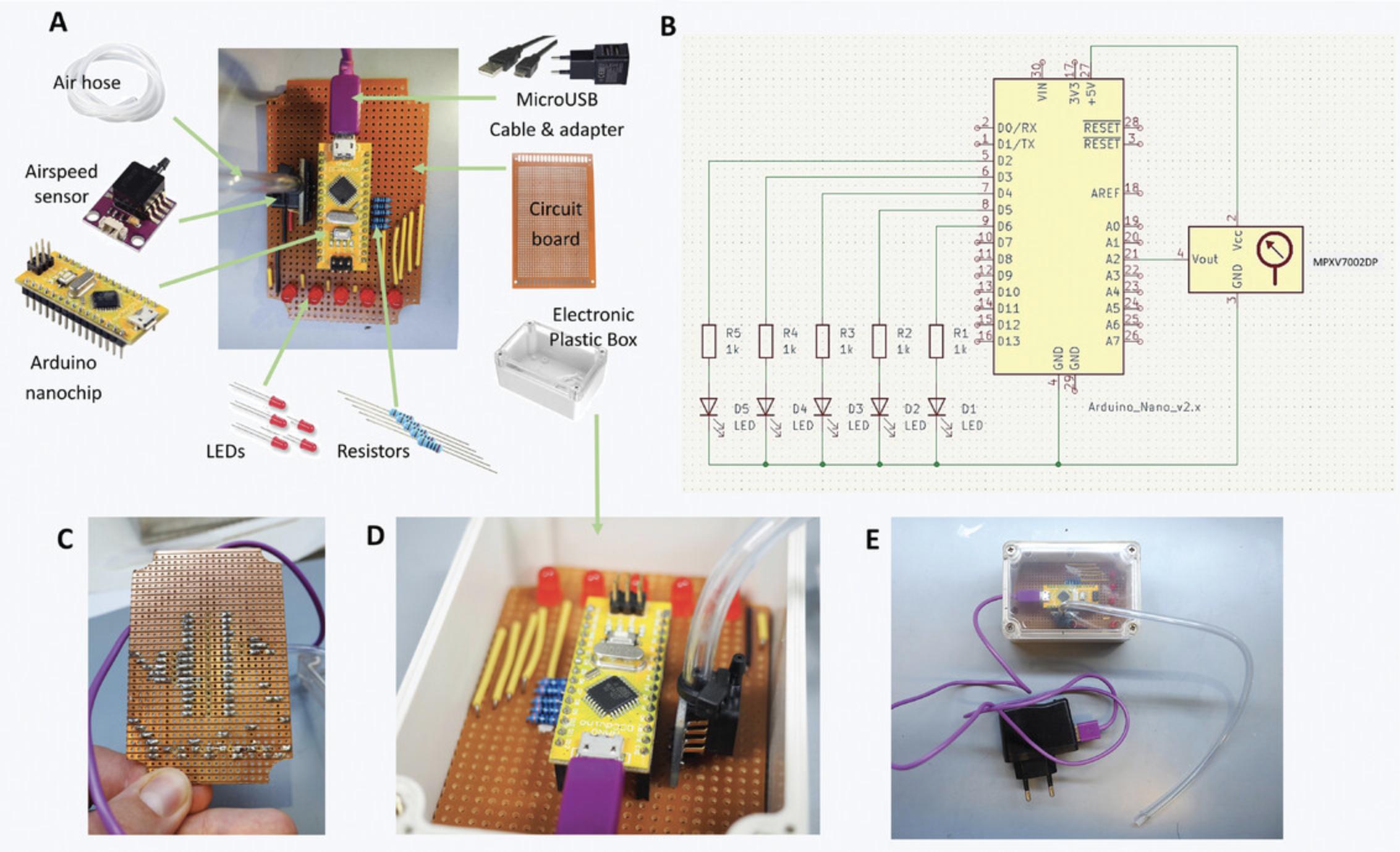
7.Set-up the airspeed sensor and nanochip.
8.Assemble the circuitry of the intubation confirmation module following the electrical scheme in Figure 9B.
-
Cut the circuit board to a size that will fit into the electronic box.
-
Solder the different parts of the circuitry into the circuit board (Fig.9C).
CAUTION: Take necessary safety precautions for soldering. Never touch the heated soldering iron, as this could result into serious burns. We strongly advise asking for an electrician's help if you do not know how to do this properly.
9.Test whether the module is working.
-
Attach the air hose to the pitch of the airspeed sensor and connect the microUSB-USB 2.0 cable and adapter to the microUSB port.
-
Plug the adapter into the power supply.
-
Gently blow some air into the air hose.
A functioning module will show a blinking LED left and right. The module may also be tested on an intubated mouse (see Basic Protocol1). Videos1and2also demonstrate how the module works when constructed properly.
Basic Protocol 1: MOUSE ENDOTRACHEAL INTUBATION
This protocol presents a simple, inexpensive, and non-invasive procedure to perform mouse endotracheal intubation. This will involve the use of an intubation platform and confirmation module, presented in Support Protocol 3.Furthermore, an external LED light source is needed as a guide for intubation (Fig. 10). It is important to properly anesthetize the animal with the recommended injection anesthetics and follow necessary animal handling guidelines.
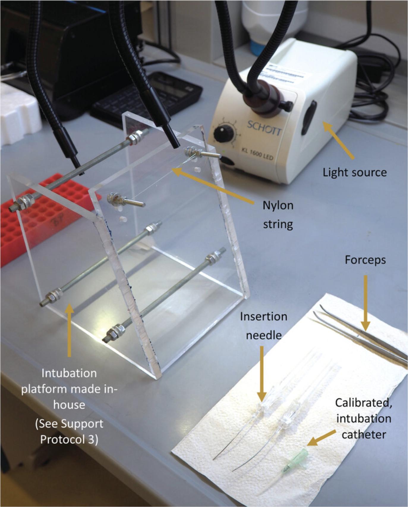
NOTE : All protocols involving animals must be reviewed and approved by the appropriate Animal Care and Use Committee and must follow regulations for the care and use of laboratory animals.
Materials
-
Mouse
-
Ketamine/xylazine cocktail (see recipe)
-
Vidisic® Eye Gel (2 mg/g Carbomerum 980; Bausch+ Lomb Czech Republic, Over-the-counter) or alternative ophthalmic ointment with Petrolatum and Mineral oil
-
Intubation platform (made in-house, see Support Protocol 3)
-
Blunt ended bent insertion needle
-
Insyte catheter 18G 30 mm (BD, Ref. No. 381244)
-
KL1600 LED cold light source (Schott, Part. No. 150 600)
-
Bent forceps
-
Intubation confirmation module (made in-house, see Support Protocol 3)
-
Insulin syringe with needle 500 or 1000 µl (Terumo™, 8SS01H25161)
-
Additional reagents and equipment for injection of rodents (see Current Protocols article: Donovan & Brown, 2006)
1.Weigh the mouse.
2.Anesthetize the mouse by intraperitoneally injecting (Donovan & Brown, the calculated dosage of ketamine/xylazine cocktail.
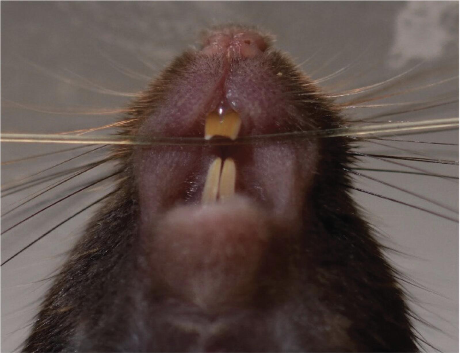
3.Secure the anesthetized animal to the platform by attaching the mouse to the nylon string of the intubation platform via an upper incisor (Fig. 11).
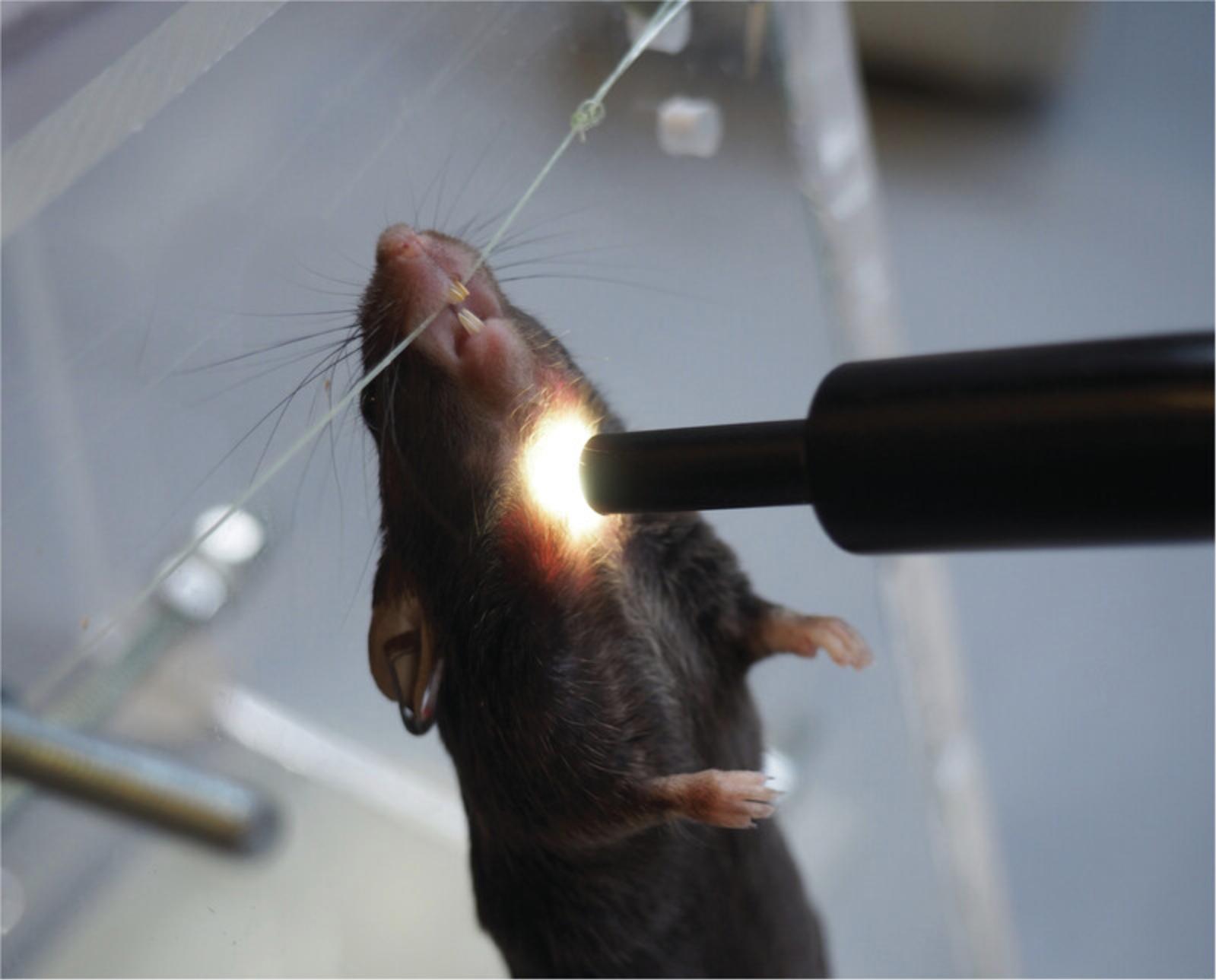
4.Illuminate the windpipe of the animal by positioning the flexible light-guides from the cold light source just below the larynx (Fig. 12).
5.Put the catheter on the needle by sliding the catheter completely over the bent, blunt-ended insertion needle.
6.Intubate the mouse.
- a.
Grab the tongue of the mouse with the bent forceps.
If the mouse reacts, wait 2 min and repeat the procedure. If the mouse is still not asleep after that time, inject 50 µl of ketamine/xylazine i.p. for intubations and wait 5 min. Write down the extra injection on the lung function report.
- b.Take the tongue between index and middle finger of the left hand.
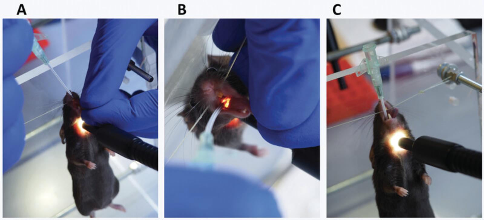
- c.Pull on the tongue until the mouth is wide open (Fig. 13A).
- d.
Look into the mouth and find the larynx (Fig. 13B).
The trachea should light up as a bright spot. If not, poke lightly with the blunt insertion needle just below the larynx until the bright spot becomes visible.
- e.Insert the bent needle, about 1 cm, into the bright spot of the trachea.
- f.
Slide the catheter into the trachea (Fig. 13C).
You should feel some resistance before getting in. Put the catheter so that the attachment part is about 0.5 cm above the nose (Fig. 18B).
7.Confirm if the intubation was done correctly.
-
Attach the tubing of the intubation confirmation module to the catheter tube (Fig.9E).
-
Assess the correctness of intubation.
If the LEDs start to blink left-right, on and off in synchronization with the breathing, intubation is done correctly. If not, restart procedure from step 5. Refer to Videos1and2for the demonstration of how the module works.
Basic Protocol 2: ASSESSMENT OF MOUSE BASAL LUNG FUNCTION
The protocol below describes the measurement of mouse lung function without introduction of any modifying agent. This protocol requires the experimenter to have prior training with the assembly of the FlexiVentFX™ System and intubation of a mouse. Both prerequisite procedures are described above.
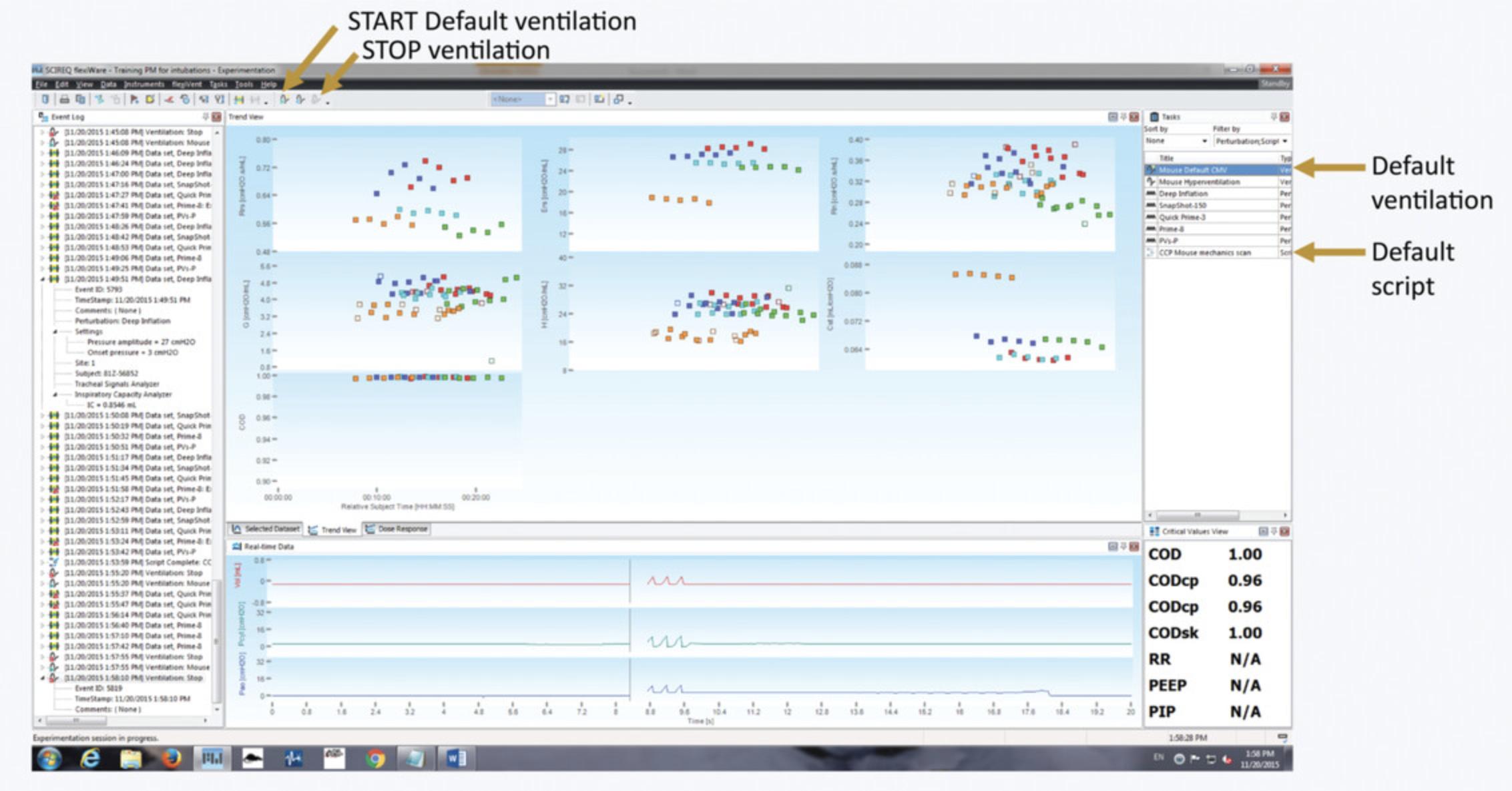
For the management of the study, data acquisition, review, and recording, FlexiWare software is needed. Refer to the FlexiWare User Manual for setup, installation, and registration. Follow Support Protocol 2 for database management. Figure 14 shows an overview of the FlexiWare software interface.
NOTE : All protocols involving animals must be reviewed and approved by the appropriate Animal Care and Use Committee and must follow regulations for the care and use of laboratory animals.
Materials
- Assembled FlexiVentFX™ Base Unit and Module (Scireq Inc.; see Support Protocol 1)
- FlexiWare Software (Scireq Inc.)
- Anesthetized and intubated mouse (see Basic Protocol 1)
- 12 × 12 × 4.2 cm styrofoam platform (see step 9b.i)
- Heating mat (Beurer, S8-S1)
- Pressure manometer 3.0 kPa (Scireq Inc.)
1.Assemble the FlexiVentFX™ System.
2.Check the size of the database.
3.Switch on the FlexiVentFX™ and start the software.
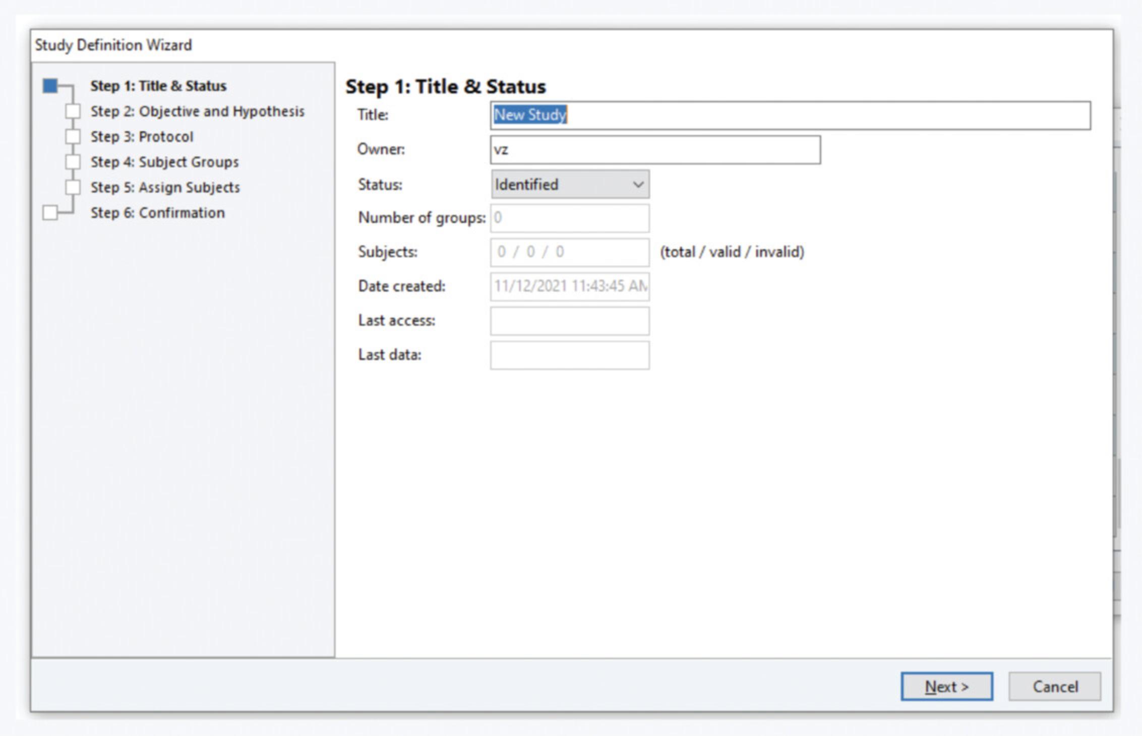
4.Select or create the study. In the study selection window, select the appropriate study. If the study you need is not defined yet (Fig. 15):
- Click on the‘Create a new Study’button on the left bottom corner or go toFilemenu >New Study. Fill in theTitlein theStudy Definition WizardStep 1
A naming convention applies, as detailed in the Support Protocol2.
Fill in your complete name in the studyOwnerfield.
-
Fill in the objective, hypothesis, and protocol in steps 2 and 3.
-
Assign the groups in step 4.
At least one group needs to be defined. For example, we create only one group called ‘Default’. For other studies, define groups according to your needs.
- Assign subjects in step 5. Select the virtual mouse called ‘Setup’ or ‘Setupx’, where x is an integer, and move it to the right column.
If there is no mouse with that name in the database, create it by clicking on ‘Subject Management’ in the bottom right corner of the window. Click on the mouse icon and the ‘+’ sign in the window that pops up. In the subject identifier, typeSetupand in the ‘Last weight’ field put25. Click OK. If the software complains that that mouse already exists in the database, rename it toSetupx.
-
Check the study definition in step 6 and click on‘Finish’.
-
Select the study you just created and click ‘OK’.
5.Select template and virtual ‘ Setup ’ mouse.
-
Select the necessary study template (e.g.,‘CCP mouse mechanics scan’) and click ‘OK’.
-
In the ‘Session properties’ window, fill in your full name in the ‘Operator’ field
-
Check that the piston arm is well mounted on the motor arm (see Support Protocol1, step 2). Click ‘OK’.
If only the ‘Setup’ or ‘Setupx’ mouse is defined in the study the ‘Subject weight’ window will pop-up. Click ‘OK’. If other mice have been defined, select the ‘Setup’ or ‘Setupx’ mouse from the list and move it to the right column by double-clicking on it or by selecting it. Click the arrow on the right, then click ‘OK’.
6.Calibrate channels if requested.
- a.Allow for the transducers to heat up, after which the ‘ Calibration Wizard ’ window will pop-up.
- b.If the calibration has expired, check the boxes in front of the channels and click ‘ Next ’.
- c.For step 2: First value: zero (atmosphere) , attach the tubing of the manometer to the tubing of the FlexiVentFX™ system. Open the ‘3-way’ tap so that the tubing is connected to the open air (white tap, forming a cross with the three openings of the tap). Aspirate air with the syringe (Fig. 16A).
- d.For the ‘ First value: zero (atmosphere) ’ click ‘ Next ’.
- e.For step 3: Second Value: Known Pressure , close the ‘3-way’ tap (white tap over the side-branch opening) and inject air until the manometer shows 300 mm H2O of pressure, hold the syringe at that pressure (Fig. 16B), and click ‘ Next ’. Check that the value says 300 mm H2O, and click ‘ Next ’. Click ‘ Next ’ when the calibration results are shown.
- f.Repeat steps c–e for the airway opening pressure calibration.
- g.On the window ‘ Calibration complete ’, click ‘ Finish ’.
- h.On the window with the tube calibration, click ‘ Cancel ’.
- i.On the window with ‘ Start default ventilation ’, click ‘ No ’.

7.Change subject and start tube calibration.
- a.Take the mouse you need to measure out of its cage, write down its ID number on the report file, and weigh it.
- b.Go to ‘ Edit ’ > ‘ Edit Site Assignment ’ in the FlexiWare software.
- c.Double click on the mouse in the right column to remove it from the site. Uncheck the box ‘ This experiment was terminal ’ for mice that were intubated or for the virtual ‘ Setup ’ or ‘ Setupx ’ mouse.
- d.Select the mouse to be measured from the list on the left and assign it to the measuring site by double-clicking on it or by clicking the arrow to the right.
- e.
Create a new mouse as described above if the mouse is not in the list.
Use the full mouse identifier as ‘Subject identifier’ and input the animal's weight. You can assign the mouse to an experimental group if needed. Mice will automatically be assigned to the first group defined if you do not assign groups.
- f.Click ‘ OK ’ and confirm that the weight is correct in the ‘ Subject weight ’ window to start the tube calibration.
- g.Close down a tube by putting a brown cap over it and attach it to the tubing of the FlexiVentFX™ (Fig. 17A and B). Click on ‘ Next ’ three times to start the ‘ Closed tube calibration ’.
- h.
Once the closed tube calibration has gone through all perturbations, remove the brown cap from the tube (Fig. 17C) and click ‘ Next ’ to start the ‘ Open tube calibration ’. Once this is done, the tube can be used for intubation.
Tube calibration must pass an acceptable range for the intubation catheter to be useful for measurement. This can be checked in the Calibration Results. For the FX1 module Deep Inflation RI, the value should not exceed 2000 cmH2O·s/ml. For the FX2 module, the limit is 1125 cmH2O·s/ml.

8.Intubate the mouse.
9.Start the ventilation and attach the mouse to the ventilator.
-
Start the ventilation by pressing the ‘Start default ventilation’ icon on the top menu or by selecting ‘Mouse default CMV’ in the menu on the right side of the screen (Fig.14).
-
Attach the mouse to the ventilator and check the following points: Alignment of the tube and the trachea.
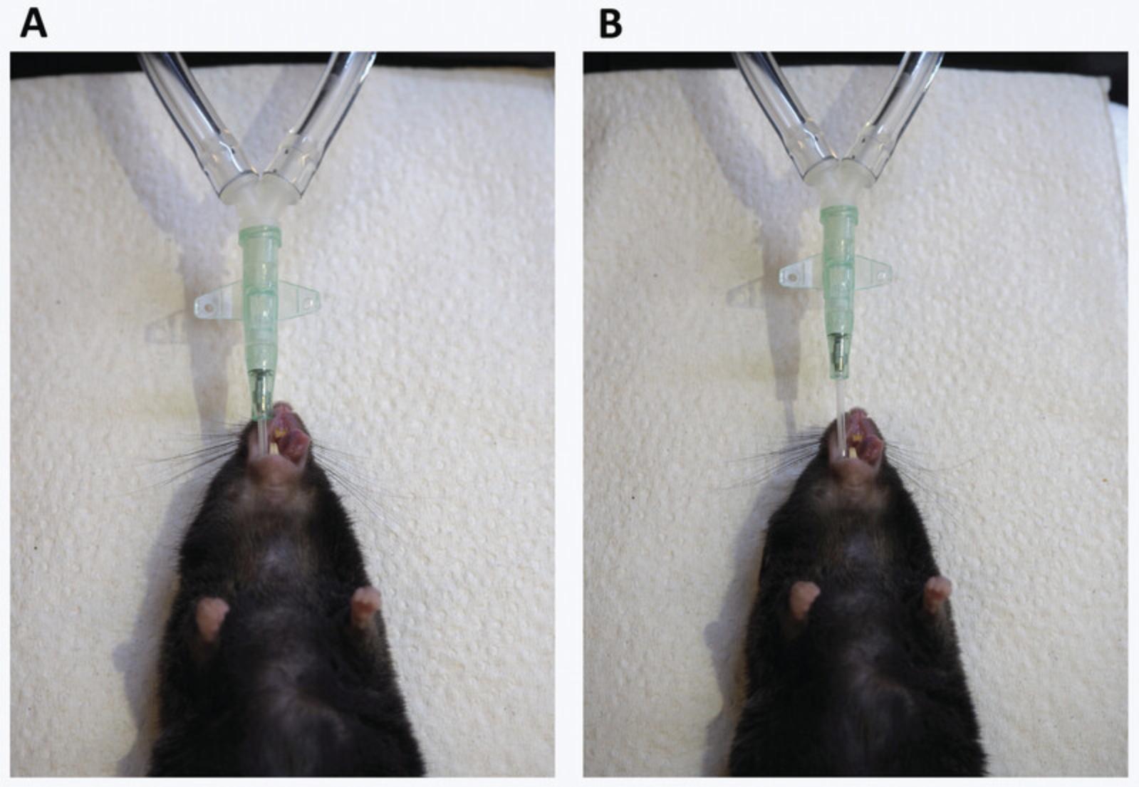
Put the styrofoam platform in front of the FX module. The platform can be made from an ordinary Falcon tube holder or cover of a box. The tubing port will be above the platform (Fig.17BandC). The intubation tube should form a straight line with the tubing port, and no angle should be present at all, or it will skew the measurement. We optimized the height of the styrofoam platform to be 4.2 cm. If necessary, raise the mouse a bit by putting some tissue under it.
Insertion of the intubation tube in the trachea.
Check that the tube is not inserted too deeply (Fig.18A), which can happen when attaching the mouse to the ventilator. The attachment of the tube should be approximately 0.5 cm from the nose of the mouse (Fig.18B).
Check that the tube attachment is fully inserted over its connector to reduce leakage to a minimum and to have a comparable situation as when the tube was calibrated.
- Check the respiratory curve (airway opening pressure).
If the pressure is too high or irregular, the tube is probably in the esophagus. Remove the mouse immediately and redo the intubation. Please check Video3for the appearance of the respiratory curves in different perturbations.
10.Check for leakage.
11.Start the script.
-
Start the script by double-clicking it on the list on the right of the screen (Fig.14).
-
The script will run for 1 min before doing two deep inflations. Check these to make sure there are no leaks (see step 10), and press ‘OK’ if no obvious leakage can be detected.
-
Write down the number of failed perturbations on the report sheet during measurements.
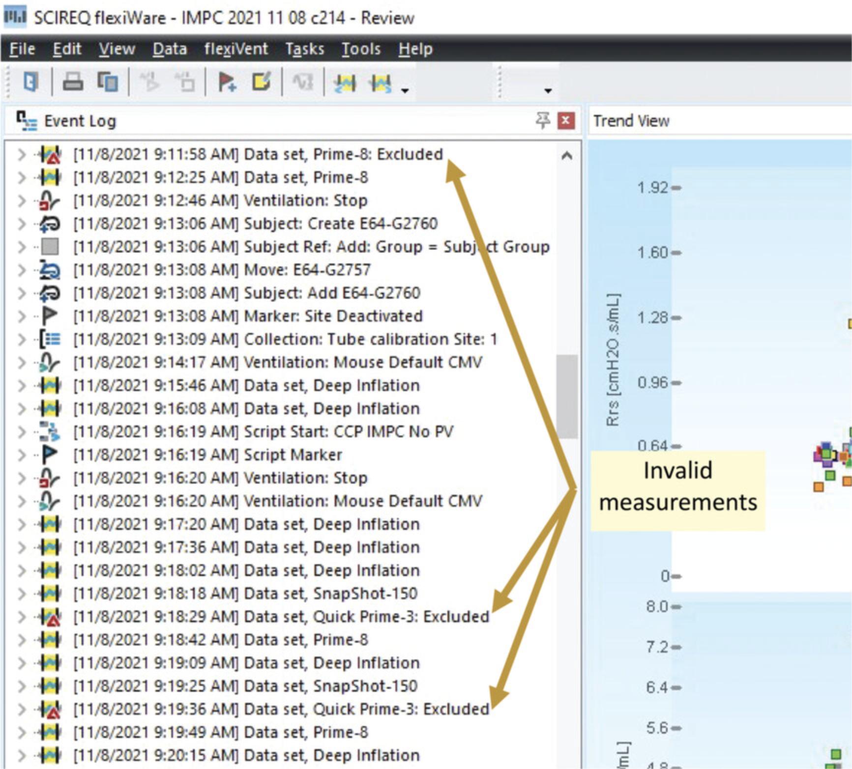
12.Repeat invalid measurements (Fig. 19).
13.Remove mouse from the FlexiVentFX™.
-
Switch back to default ventilation if the ventilator was set to hyperventilation. Leave this on for 1 min before proceeding to the next step.
-
Switch off the ventilation by pressing the ‘Stop ventilation’ icon on top of the screen (Fig.14). The airway opening pressure curve should start to show rippling after a few seconds. If this does not appear after 15 s, switch the ventilation back on and wait for a few minutes, before retrying.
Please refer to Video5for a demonstration of this step.
-
When the rippling appears, the mouse can be disconnected from the FlexiVentFX™ and extubated in case intubation was used. The ventilation can be stopped. When intubation was used and mice need to recover, put them on a heating mat.
14.Restart from step 7 for a new mouse.
15.After the experimental session, clean and dry the adaptor, tubings, and system expiratory valve by following the manufacturer's instructions.
REAGENTS AND SOLUTIONS
Ketamine/xylazine cocktail
- Ketamine (100 mg/ml; Bioveta, A.S., Narkamon 100 mg/ml)
- Xylazine (20 mg/ml; Bioveta, A.S., Rometar 20 mg/ml)
- Water for injection (B. Braun Medical s. r. o., cat no. 3601013)
- For a 10-ml cocktail, mix 1000 µl of 100 mg/ml ketamine plus 500 µl of 20 mg/ml xylazine plus 8500 µl water for injection.
COMMENTARY
Background Information
The lungs are the primary organs for respiration. The oxygen in the air breathed in is exchanged with carbon dioxide in the bloodstream. This happens at the terminal alveolar sacs of the bronchioles. The total lung capacity (TLC) refers to the volume of air that the lungs can take in upon the maximum inspiration effort. TLC can be broken down into different lung volumes and capacities at different phases of the respiratory cycle (Fig. 20A). The tidal volume represents the volume of air moving in or out of the lungs during quiet breathing. Upon maximal inhalation from the end-inspiratory level, the lungs can accommodate the inspiratory reserve volume. The expiratory reserve volume and residual volume represent the maximal volume of air that can be exhaled from the end-expiratory level and the volume of air remaining after maximal exhalation, respectively. These are the basic elements of the pulmonary function test measured by a spirometer, plethysmography, the dilutional helium gas method, the nitrogen gas washout method, or computed tomography (CT) (Flesch & Dine, 2012; Lutfi, 2017). Restrictive and obstructive breathing caused by pathologies like pulmonary fibrosis, asthma, COPD, and emphysema, among others, can be diagnosed by observing changes in these basic elements. The same parameters are being measured in different animal models of pulmonary pathologies (Bethany et al., 2013; Brusselle et al., 2006; Kumar, 1995; Kwak, Tsai, & DeMayo, 2004).
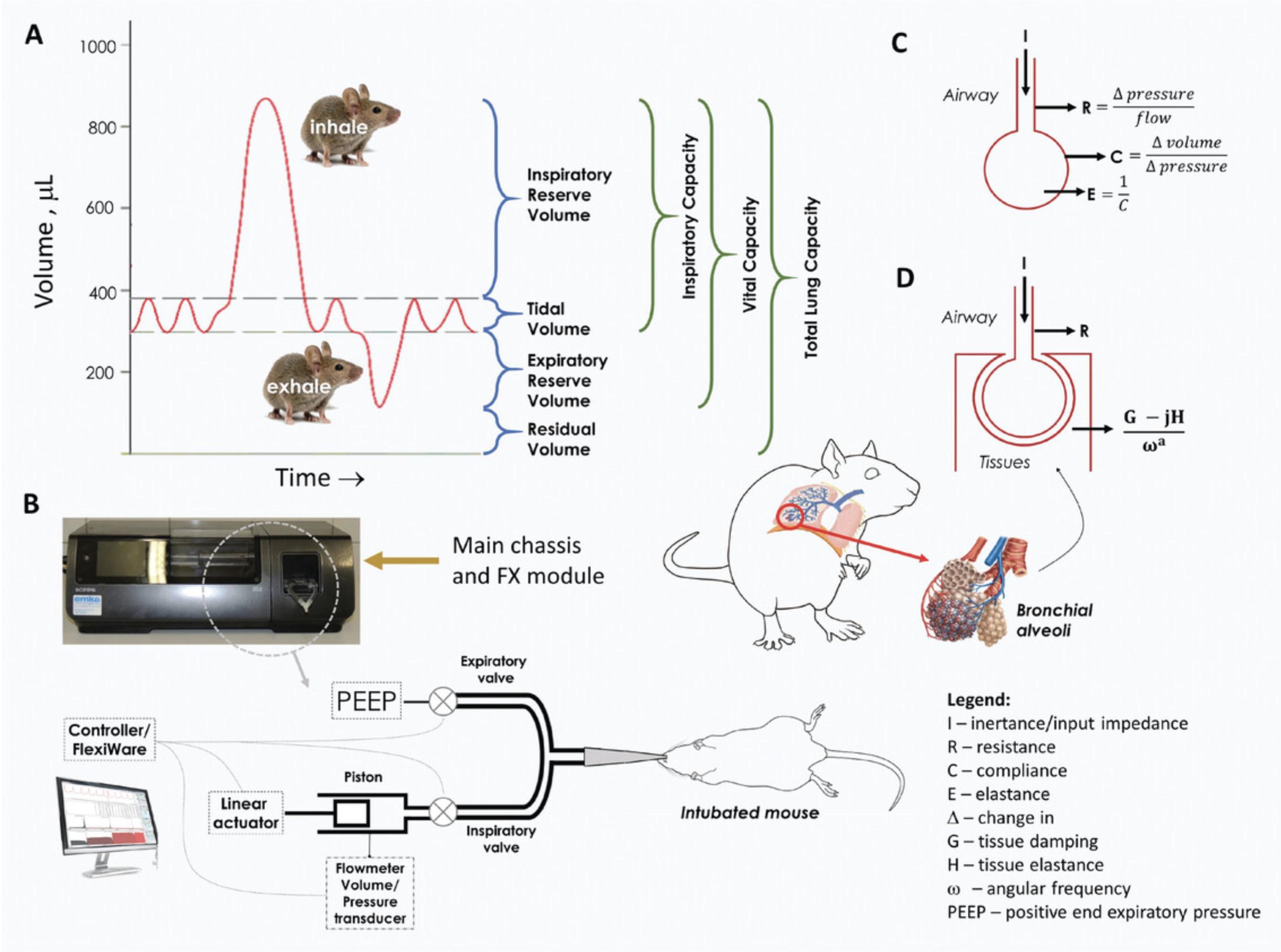
In conditions where a hospitalized patient has to be ventilated with the aid of mechanical ventilation, the basic elements mentioned above have to be supplemented with respiratory mechanics (Gertler, 2021). Respiratory mechanics refer to the expression of lung function via pressure and flow parameters, enabling the derivation of indices for pressure, volume, compliance, elastance, and resistance (Gertler, 2021). Artificial ventilators, which facilitate the patient's respiration, monitor lung mechanics in hospitals. This has become even more relevant during the COVID-19 pandemic, during which ventilators have been used for patients that require assisted breathing. Knowledge of lung function mechanics is essential for proper optimization of the ventilator to match the patient's pulmonary status. The comprehensive discussion of lung mechanics is beyond the scope of this protocol and is discussed in detail elsewhere (Bates, 2009; Bates, Irvin, Farre, & Hantos, 2011; Gertler, 2021; Kaczka & Dellaca, 2011; Similowski & Bates, 1991).
The FlexiVentFX™ system, in simple terms, measures animal lung mechanics via forced oscillation technique (FOT), a method also being used in humans. The different parameters are derived from analyzing volume and pressure signals obtained in response to an oscillating airflow waveform of predefined frequency (perturbation or input signal) applied at the subject's airway opening (Bates & Irvin, 2003). This mechanism can be found in the FX module of the FlexiVentFX™ system with the linear actuator or piston assembly attached to the main chassis of the instrument (Fig. 20B and Support Protocol 1). The piston assembly generates the input signal. Flowmeters and pressure transducers located at various locations in the system analyze the changes in volume and pressure as the waveform moves from the source to the lungs of the subject. In simple terms, the pressure, flow, and volume ratios in relation to the frequency of the input signal give rise to the major lung mechanics parameters (Fig. 20C and D; Table 2). Depending on the type of the input signal or perturbation, different models can be used to assess lung function.
A single frequency of 150 breaths/min in a single 2.5-Hz forced oscillation from the piston adapts the linear, single-compartment model (Fig. 20C). This simple model pictures the lung as a balloon sealed over the end of a pipe which can be inflated or deflated. A known volume is sent to the subject's lungs. The flow and the changes in the pressure and volume in the airways are observed. This enables the calculation of resistance (R), elastance (E), and dynamic compliance (C), which correspond to the measurement of airway constriction, stiffness, and ability to stretch, respectively (Fig. 20C; Table 2). This model is the basis for the SnapShot-150 perturbation of the FlexiVentFX™ system. Another lung mechanics that can be modeled in the FlexiVentFX™ system is the constant-phase model. Instead of one frequency, the piston is set to deliver multiple forced oscillations at different frequencies above and below the subject's breathing frequency. In this manner, the broad range of frequencies will hit different parts of the airways which will have different responses. For example, higher frequencies can reach deeper into the alveoli of the lungs. The constant-phase model provides a mechanism for separating central conducting airways (RN: Newtonian resistance) from the alveolar tissue (H: Tissue elastance) mechanics (Fig. 20D; Table 2). In addition, the constant-phase model also provides the measurement of tissue damping (G) which reflects the amount of input signal that is lost to energy dissipation in the peripheral alveolar airways. These capabilities of the forced oscillation technique (FOT) to test different lung mechanics in animals have made it today's most precise technology for lung function assessment compared to other technologies like plethysmography (Claridge, Enelow, & Young, 2000; Robichaud, Fereydoonzad, Urovitch, & Brunet, 2015). At the time of writing, the FlexiVentFX™ is the only commercial FOT system currently available for pre-clinical measurement of lung mechanics.
The lung function assessment protocol presented here is a product of more than 20 years of improving the FOT for application in animal models of pulmonary pathologies. FOT can be done on anesthetized, tracheotomized animals, which is invasive. The orotracheal intubation technique presented in Basic Protocol 1 circumvents this primary drawback, allowing repetitive measurements in the same animals (De Vleeschauwer et al., 2011; Glaab et al., 2004). The success of the FOT measurements depends on the precision of the intubation method. We highly recommend proper training of the experimenter to prevent damaging the trachea, especially in survival procedures. Illuminating the windpipe with an LED cold light source has provided a simple but efficient way of locating the opening of the trachea without the use of a sophisticated instrument. Methods like utilization of an optical fiber inserted in the IV catheter (MacDonald, Chang, & Mitzner, 2009) are available. The catheter insertion may likewise be facilitated with a guide wire (Su et al., 2016). We present in Basic Protocol 1 a unique way to validate correct intubation using a confirmation module made in-house (Support Protocol 3). This simple device ensures that the catheter is properly placed in the trachea before attachment of the mouse to the FlexiVentFX™ system. The airflow from normal breathing of the mouse is converted to a signal that can be read from the LED lights of the module. If the catheter is inserted in the stomach or too deep in one of the bronchial tubes, the LED indicator will send an error signal (Basic Protocol 1; also see videos). Please contact us for more information on how the confirmation module was made.
Critical Parameters
Several critical points for consideration can be identified in the protocols. First, the tube calibration must pass acceptable values, as any errors or inaccuracies will be carried over to the measurement done in the animals. Second, the intubation tube must be perfectly aligned to the trachea of the intubated mouse. The animal must be at the same level as the ventilator. Using a leveled platform will ensure this, and thus prevent possible occlusion of the catheter or twisting of the trachea. Third, the intubation tube must be inserted in the trachea following the recommendation in step 9b of Basic Protocol 2, to ensure proper maneuvering of air into and out of the lungs. Finally, fourth, the deep inflation in step 10 of Basic Protocol 2 must be carried out to guarantee that there is no leakage or catheter obstruction.
Troubleshooting
See Table 1 for a troubleshooting guide related to these protocols.
| Problem | Possible cause | Solution |
|---|---|---|
| Tube calibration values outside acceptable range | The attachment of the catheter is not locked properly | Tighten the cannula attachment and re-perform the calibration |
| Irregular deep inflation perturbations | Leakage in the system |
|
| Invalid measurements |
|
Understanding Results
The FlexiWare software automatically calculates different parameters associated with each perturbation. Table 2 summarizes the different perturbations and parameters covered by the script of the protocol.
| Perturbation | Description | Parameters measured [Unit] = definition |
|---|---|---|
| Deep inflation | Deep inflation of the lungs to a specified pressure, typically 30 cmH2O, followed by a few seconds of breath hold | TLC [ml] = Total Lung Capacity (≈ IC = Inspiratory Capacity) |
| SnapShot-150 | Matching the ventilation frequency of 150 breaths/min in a single 2.5 Hz, sinusoidal forced oscillation waveform |
Single- Compartment Model: R [cm H2O•s/ml] = Resistance of the respiratory system (resistance of the central or conducting airways ≈ airway constriction) E [cm H2O/ml] = Elastance of the respiratory system (elastic stiffness of the respiratory system at the ventilation frequency ≈ stiffness) C [ml/cm H2O] = Dynamic Compliance (characterization of the overall elastic properties that the respiratory system needs to overcome during tidal breathing to move air in and out of the lungs ≈ ability to stretch) |
|
Quick prime-3 prime-8 |
Multiple frequency, forced oscillation waveforms lasting 3 or 8 s |
Constant-Phase Model: RN [cm H2O•s/ml] = Newtonian resistance (central airway constriction) G [cm H2O/ml] = Tissue damping (closely related to tissue resistance and reflects the energy dissipation in the alveoli) H [cm H2O/ml] = Tissue elastance (alveolar tissue stiffness) η = G/H (hysteresivity) or structural damping coefficient |
Different mechanics of lung function can be obtained by using this protocol with the FlexiVentFX™ system. The deep inflation perturbation provides a measurement of the inspiratory capacity, which could be affected in disease conditions like asthma, emphysema, or fibrosis. The single-frequency SnapShot forced oscillation perturbation delivers a targeted volume into the lungs of the animal. Volume, pressure, and flow signals are then fit into the classical, single-compartment model. The SnapShot perturbation provides the overall resistive and elastic properties of the respiratory system, which are important in asthma, allergic rhinitis, and drug research. The broadband-frequency Primewave forced oscillation perturbation with mathematical modeling is fitted to the constant-phase model. A prime perturbation generates the respiratory input impedance, which is interpreted by contributing factors mentioned in the table above. The prime perturbations can be used to partition the subject's airway (RN) and lung-tissue (G and H) mechanics.
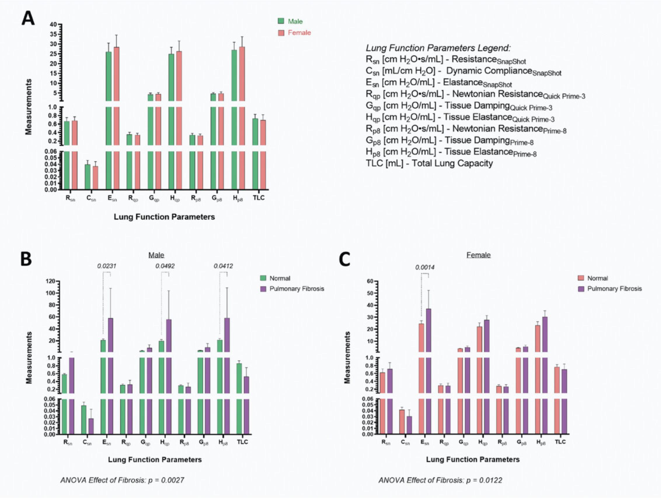
Figure 21 shows typical lung function measurements obtained by following this protocol. There is no significant difference in lung function parameters between male and female, 16-week-old, C57BL/6N mice (Fig. 21A). Both the Quick Prime-3 and Prime-8 perturbations gave comparable values for the Newtonian resistance, tissue damping, and elastance. Furthermore, the measurements for resistance and elastance using the single-compartment or contrast-phase models are similar. We have likewise observed this in a lung fibrosis model that results in increased elastance in males using both models of dynamics (Fig. 21B). Female mice suffering from pulmonary fibrosis had significantly higher elastance of the respiratory system compared to normal mice (Fig. 21C). The contrast-phase model did not detect this suggesting sex differences. However, a significant main effect of fibrosis was observed for both males and females, indicating impaired lung function in the disease state.
Time Considerations
The assembly of the FlexiVentFX™ system in Support Protocol 1 takes 15 min. Once assembled, the FX Module may stay attached to the main chassis for successive measurements. The FX1 and FX2 tubing ports may be disassembled from the system for cleaning. Management of the FlexiWare database takes 30 min. Mouse endotracheal intubation in Basic Protocol 1 can be broken down as follows: mouse weighing and anesthesia for at least 10 min, placing the mouse in the platform and illumination of the windpipe for 2 min, and the actual intubation for 30 s for a well-trained individual. If confirmation of correct intubation with the module is to be done, 1 min needs to be allotted. The construction of the intubation platform and confirmation module will take a day provided all materials and knowledge of electronics are available.
The complete time considerations for Basic Protocol 2 for the assessment of mouse lung function may vary depending on the animal and experimental set-up. The creation of a new study in the FlexiVent software and setting up a virtual mouse may take 20 min. The calibration of channels via the calibration wizard will take around 4 min. Each tube calibration will take another 3 min. The attachment of the anesthetized mouse to the ventilator, starting the ventilator, and checking for correct tube alignment and intubation will all take 2 min. An additional 2 min should be used for checking for leakage via the respiratory curve. Running the script of the experiment presented in this protocol will take 7 min. The time needed for the repetition of invalid measurements depends on how many measurements must be repeated.
Acknowledgments
The Czech Centre for Phenogenomics at the Institute of Molecular Genetics supported by the Czech Academy of Sciences RVO 68378050 and by the project LM2018126 Czech Centre for Phenogenomics provided by Ministry of Education, Youth, and Sports of the Czech Republic. The authors also would like to thank Pavel Semerád of The Secondary Industrial School of Electrical Engineering in Pardubice.
Author Contributions
Roldan Medina De Guia : formal analysis, methodology, visualization, writing original draft, writing review and editing; Vaclav Zatecka : data curation, formal analysis, investigation, methodology, validation, writing review and editing; Jan Rozman : resources, supervision, writing review and editing; Jan Prochazka : conceptualization, project administration, resources, supervision, writing review and editing; Radislav Sedlacek : funding acquisition, resources, supervision, writing review and editing.
Conflict of Interest
The authors have no conflicts of interest to declare. All authors have seen and agree with the contents of the manuscript and there is no financial interest to report.
Open Research
Data Availability Statement
The data that support the findings of this study are available from the corresponding author upon reasonable request.
Literature Cited
- Bates, J. H. (2009). Lung Mechanics: An Inverse Modeling Approach. Cambridge: Cambridge University Press.
- Bates, J. H., & Irvin, C. G. (2003). Measuring lung function in mice: The phenotyping uncertainty principle. Journal of Applied Physiology , 94(4), 1297–1306. doi: 10.1152/japplphysiol.00706.2002
- Bates, J. H., Irvin, C. G., Farre, R., & Hantos, Z. (2011). Oscillation mechanics of the respiratory system. Comprehensive Physiology , 1(3), 1233–1272. doi: 10.1002/cphy.c100058
- Bethany, B. M., Lawson, W. E., Oury, T. D., Sisson, T. H., Raghavendran, K., & Hogaboam, C. M. (2013). Animal models of fibrotic lung disease. American Journal of Respiratory Cell and Molecular Biology , 49(2), 167–179. doi: 10.1165/rcmb.2013-0094TR
- Brusselle, G. G., Bracke, K. R., Maes, T., D'Hulst, A. I., Moerloose, K. B., Joos, G. F., & Pauwels, R. A. (2006). Murine models of COPD. Pulmonary Pharmacology & Therapeutics, 19(3), 155–165. doi: 10.1016/j.pupt.2005.06.001
- Claridge, J. A., Enelow, R. I., & Young, J. S. (2000). Hemorrhage and resuscitation induce delayed inflammation and pulmonary dysfunction in mice. Journal of Surgical Research , 92(2), 206–213. doi: 10.1006/jsre.2000.5899
- De Vleeschauwer, S. I., Rinaldi, M., De Vooght, V., Vanoirbeek, J. A., Vanaudenaerde, B. M., Verbeken, E. K., … Janssens, W. (2011). Repeated invasive lung function measurements in intubated mice: An approach for longitudinal lung research. Laboratory Animals , 45(2), 81–89. doi: 10.1258/la.2010.010111
- Donovan, J., & Brown, P. (2006). Parenteral injections. Current Protocols in Immunology , 73, 1.6.1–1.6.10. doi: 10.1002/0471142735.im0106s73
- Flesch, J. D., & Dine, C. J. (2012). Lung volumes: Measurement, clinical use, and coding. Chest , 142(2), 506–510. doi: 10.1378/chest.11-2964
- Gertler, R. (2021). Respiratory mechanics. Anesthesiology Clinics , 39(3), 415–440. doi: 10.1016/j.anclin.2021.04.003
- Glaab, T., Mitzner, W., Braun, A., Ernst, H., Korolewitz, R., Hohlfeld, J. M., … Hoymann, H. G. (2004). Repetitive measurements of pulmonary mechanics to inhaled cholinergic challenge in spontaneously breathing mice. Journal of Applied Physiology , 97(3), 1104–1111. doi: 10.1152/japplphysiol.01182.2003
- Kaczka, D. W., & Dellaca, R. L. (2011). Oscillation mechanics of the respiratory system: Applications to lung disease. Critical Reviews in Biomedical Engineering , 39(4), 337–359. doi: 10.1615/critrevbiomedeng.v39.i4.60
- Kumar, R. K. (1995). Experimental models in pulmonary pathology. Pathology , 27(2), 130–132. doi: 10.1080/00313029500169722
- Kwak, I., Tsai, S. Y., & DeMayo, F. J. (2004). Genetically engineered mouse models for lung cancer. Annual Review of Physiology , 66, 647–663. doi: 10.1146/annurev.physiol.66.032102.134301
- Lutfi, M. F. (2017). The physiological basis and clinical significance of lung volume measurements. Multidisciplinary Respiratory Medicine , 12, 3. doi: 10.1186/s40248-017-0084-5
- MacDonald, K. D., Chang, H. Y., & Mitzner, W. (2009). An improved simple method of mouse lung intubation. Journal of Applied Physiology , 106(3), 984–987. doi: 10.1152/japplphysiol.91376.2008
- Robichaud, A., Fereydoonzad, L., Urovitch, I. B., & Brunet, J. D. (2015). Comparative study of three flexiVent system configurations using mechanical test loads. Experimental Lung Research , 41(2), 84–92. doi: 10.3109/01902148.2014.971921
- Similowski, T., & Bates, J. H. (1991). Two-compartment modelling of respiratory system mechanics at low frequencies: Gas redistribution or tissue rheology? European Respiratory Journal , 4(3), 353–358. Retrieved from https://www.ncbi.nlm.nih.gov/pubmed/1864351
- Su, C. S., Lai, H. C., Wang, C. Y., Lee, W. L., Wang, K. Y., Yang, Y. L., … Liu, T. J. (2016). Efficacious and safe orotracheal intubation for laboratory mice using slim torqueable guidewire-based technique: Comparisons between a modified and a conventional method. BMC Anesthesiology , 16, 5. doi: 10.1186/s12871-016-0173-6

