Oxygen Evolution Measurement: Light Curve for Algae
Steven J Burgess, Chandra Davies
Abstract
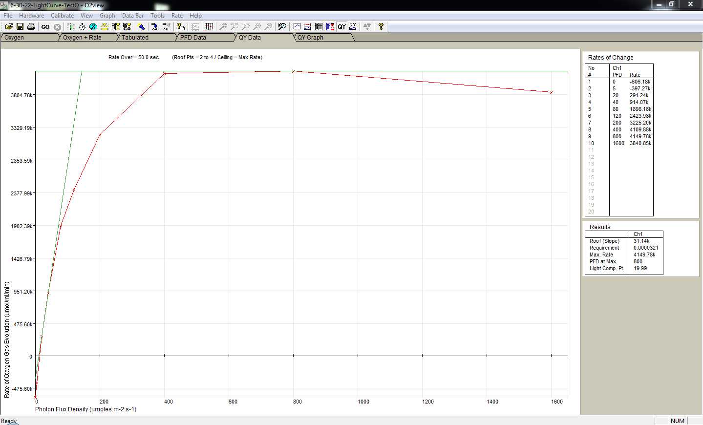
Thanks to a lovely combination of trial and error I present to you an optimized* protocol for using an oxygen electrode to create a light curve for Ostrecoccus tauri . The light curve can be used to determine what light intensity is ideal for photosynthesis in O. tauri , which can then inform the light conditions for a subsequent bicarbonate curve. An O. tauri bicarb curve could potentially indicate (when compared to other algal bicarb curves) whether or not this species has a carbon-concentrating mechanism.
*This protocol could be further optimized by making a growth curve for O. tauri first.
*The protocol is written for O. tauri and can be adapted to other algal species. When adapting it will be necessary to reassess optimal cell density for measurements, and consider the choice of buffer for washing and incubating cells. ASW is used in this situation but will not be suitable for fresh water species
Before start
Have a checklist - (1) water jacket, (2) stirrer, (3) lid as a reminder to do these steps each time
Steps
Prepare 0.5M NaHCO3 Solution
Prepare 0.5 M NaHCO3 Solution
Dispense 10mL of dH2O into a 50 mL centrifuge tube
Weigh out 0.420g of sodium bicarbonate
Add 0.420g of sodium bicarbonate to the dH2O
Close lid and invert until everything is dissolved
Prepare the electrolyte
Prepare the electrolyte
Weigh out 17.5g of anhydrous KCl salt
Pour the salt into a 500mL glass bottle
Measure 100mL of dH2O
Pour the water into the same bottle as salt
Close the lid and swirl the bottle with mild aggression until salt is dissolved
Clean and Prepare the electrode
Clean and Prepare the electrode
Start the water jacket going at 25 oC so it’s ready by the time your electrode is prepared
Use the membrane applicator to secure the small O-ring over the membrane and cigarette paper at the base of the electrode

Place the large O-ring in the indentation outside the well
Tuck any extra edges of membrane into the well using forceps so it doesn't touch the larger O-ring

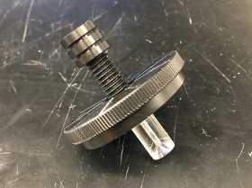
Attach the cord that connects the control unit to the electrode, then fit the disc into the bottom of the electrode chamber (pictures in steps 4.1-4.2).
Open O2View program on laptop
Add port cover blanks to 3 of the open ports and insert the red light to the 4th open port.
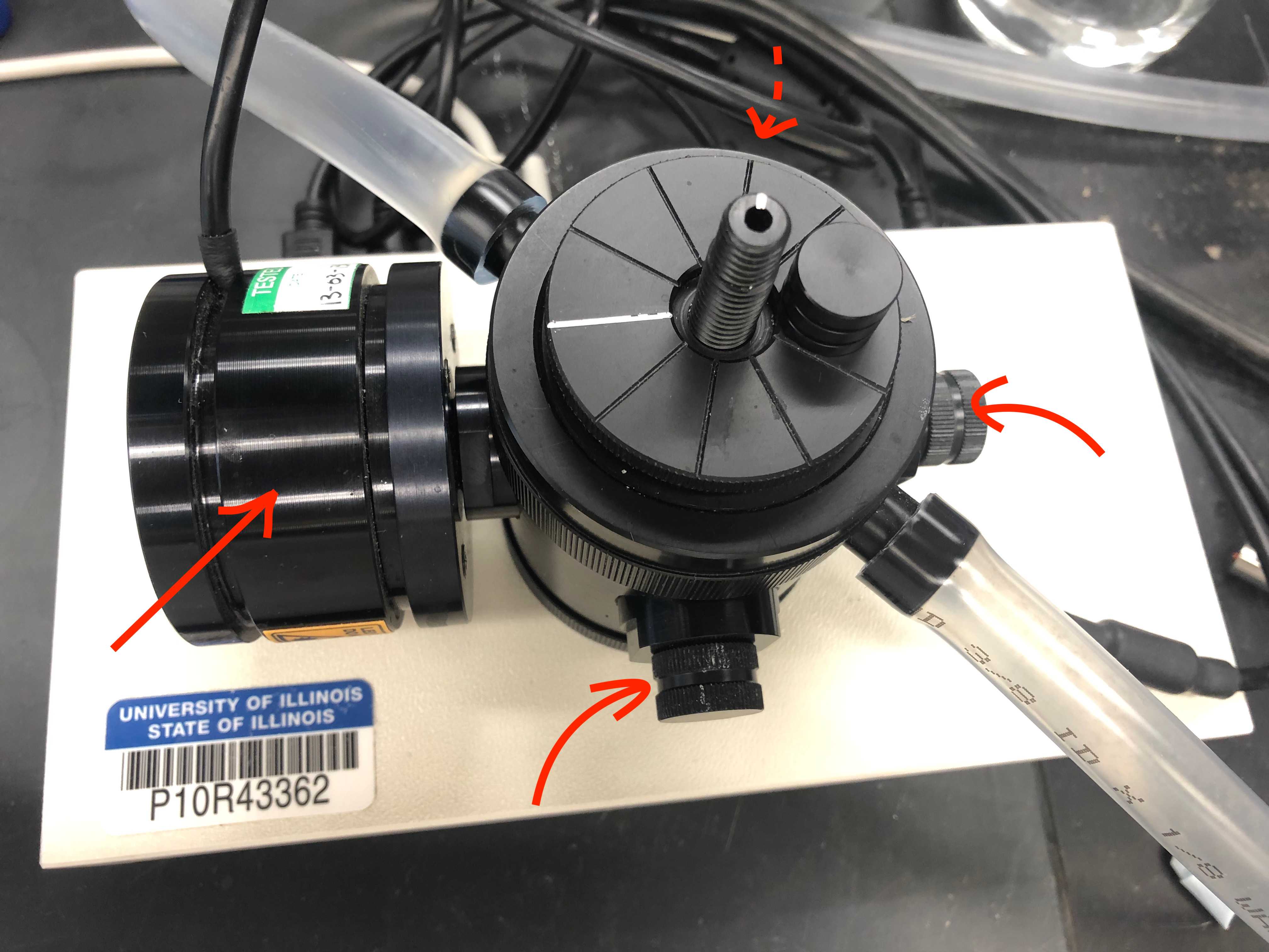
Insert the light sensor to the top opening of the electrode chamber, ensuring the circular patch is facing the light source (pictures in steps 4.1-4.2).
Dampen a cotton bud with dH2O and use it to pick up a thin layer of Hansatech Rapid Electrode Disc Polish to clean the electrode
Circle the inside of the well with the polish
Polish the platinum electrode as well.
Use a clean, dH2O-dampened cotton bud to remove the residual polish. A kimwipe can be used to dry the electrode after this step, too.
Use a disposable Pasteur pipette to add a drop of electrolyte to the top of the platinum electrode.
Add 3-5 drops of water so that the silver band inside the well is completely covered.
Cut a 1.5-2 cm2 piece of thin cigarette paper to the top of the electrode.
Cut a slightly larger square of the provided PTFE membrane tape and place it on top of the paper.

Light Calibration
Light Calibration
Ensure both the light and light sensor are inserted to their appropriate ports, and that the light sensor is actually facing the light


In the O2View program, in the upper menu bar, click Calibrate > calibrate light (automatic)
This should take a few minutes but it will do it itself.
Electrode Calibration
Electrode calibration
Add 1mL of ASW to the electrode chamber
Insert plunger (hollow lid-like contraption with glass on one end. Glass end goes into the chamber)
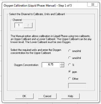
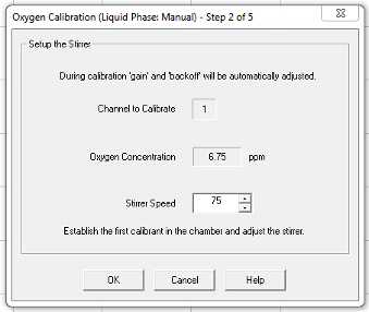
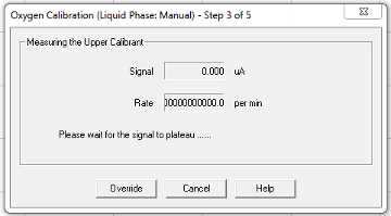
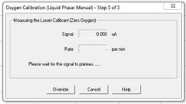
Calibrate > Liquid phase calibration (manual)
Follow the prompts that pop up on the screen
Use their default 25 μmol/mL oxygen concentration setting.
Enter stirrer speed of 75
Continue to follow prompts:
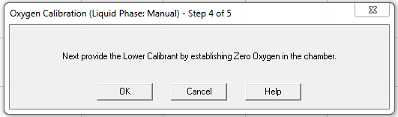
Nitrogen gas was introduced to the chamber from a large tank at the end of the bench through a tube with a 1000 μL pipette tip attached. The pipette tip goes directly into the ASW in the electrode chamber, preferably without jamming it into the electrode disc. Leave it in until the signal has plateaued and the calibration is saved.
Prepare Light Curve Culture Samples
Preparing Light Curve Culture Samples
In a flow hood, pour 25mL of a healthy culture into a 50 mL centrifuge tube
Use the paintbrush again to resuspend. Press the paintbrush against the inside of the tube when pulling it out to try and save as much of the sample as possible.
Prepare a balance with another tube of 25mL of dH2O
Centrifuge for 0h 5m 0sat 5000g and 20oC
Discard the supernatant by micropipetting
Resuspend in 10mL of ASW by gently disturbing the pellet with a small paintbrush
Balance with dH2O again in centrifuge for 0h 5m 0s, 5000g, 20 oC
Discard the supernatant
Add 1mL ASW to the pellet
Swirl the tube gently
PFD Table Set up for Light Curve
Photon Flux Density Table Set up for Light Cruve
Remove ASW from chamber
When program is done, turn off stirrer
View QY Data tab and save the file
Make sure the stirrer is still going (can turn off while removing ASW)
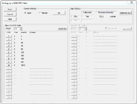
In the top menu bar, click Hardware > New PFD table
Select auto
Adjust so the following intensities of light (umoles) are selected for 1 minute each: 0, 5, 20, 40, 80, 120, 200, 400, 800, 1600. Click save if you need to close the window, otherwise leave the window up until you clock "go."
Add 900µL of culture
Add 100µL of NaHCO3 solution
Place the plunger into the chamber
Click "Go" on PFD window
Clean Up
Clean Up
Remove the sample from the electrode chamber using a pasteur pipette
Rinse the electrode disc with dH2O
Rinse the magnetic flea with dH2O
Make sure everything is gently and thoroughly dried, use a kimwipe for the electrode disc.
Repeat the same polish process as done at the beginning on the electrode/electrode disc. It's important to clean the electrode disc thoroughly right after you're done using it to prevent any tarnish buildup, which can happen after one day of use. The electrode disc should also be stored with a dehydration packet.
Make sure everything is turned off (stirrer, light)
Take out and put away the optical port blanks
Take out the light
Unscrew the bottom of the electrode chamber, careful not to let the electrode and magnetic follower fall
Pull out the electrode disk, catch the magnetic follower
Rinse the inside of the electrode chamber with dH2O
Take the O-rings off the electrode and rinse them with dH2O
Take off the membrane and paper from the electrode and dispose of them in the bio-waste bin
