Image processing to generate first-level product
Wei-Ping Chan
Abstract
Details could be found in the Supplementary Information of "A high-throughput multispectral imaging system for museum specimens"
Steps
Img Synchronization
Setting up rclone
rclone is a cloud file-manager operable at the command-line level which is used here to copy image files uploaded to and stored on Google Drive to a directory on a computing cluster. Once uploaded to the cluster, these image files may then be used in downstream high-throughput analyses.
Setting up the connection to the Cloud Drive by following the official rclone documentation
rclone works under a CenOS6 environment. Load the environment for rclone before loading the rclone module (see step 1.3)
#load functional working environment (centos 6)
module load centos6/0.0.1-fasrc01
```(Note that this is s step implemented specifically for the cluster at Harvard since rclone is available on the CentOS6 environment)
#load rclone module (centos 6)
module load rclone
Synchronizing images from the cloud drive. A cron job launching this command can also be established to monitor the cloud drive regularly so the newly uploaded images will be synched to the target directory automatically. Note that if the token for the cloud drive is password-protected, the interactive bash mode may be more secure as the cron job would then require you to embed your password in the script.
#rclone (linux)
srun --pty -p PARTITION_NAME -t TIME --mem 20000 rclone --transfers=8 --checkers=16 -c copy GOOGLE_DRIVE_NAME THE_DIRECTORY_ON_THE_CLUSTER
```(All variables in CAPITAL LETTERS should be specified by the user)

GOOGLE_DRIVE_NAME: The name and directory of the linked Google drive

THE_DIRECTORY_ON_THE_CLUSTER: The destination where the images go to
Img preprocessing
Preprocess the images
Prepare the corresponding specimen label file
| A | B | C | D | E | F | G |
|---|---|---|---|---|---|---|
| Drawer_name | 1 | 2 | 3 | 4 | 6 | ... |
| Drawer_1 | ### [Specimen ID] | ### | ### | ### | ### | ... |
| Drawer_2 | ### | ### | ### | ### | ### | ... |
| Drawer_3 | ### | ### | ### | ### | ### | ... |
Generalized structure of the specimen label file. It is essential that the file be formatted according to the specifications above, as downstream programs will use the values in the Drawer_name column to name drawer batch image files and the specimen IDs (denoted as ### above) to match with and name specimen images. If specimens are mislabeled in this CSV label file, they will also be misidentified in downstream analyses.

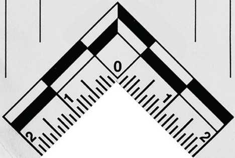
Download the MatLab scripts from the GitHub repository to the MatLab code library. Drop a clear image of the scale bar into the provided MatLab code library so it can be used to identify the scale in the images. The following image is the one corresponding to the scale used in our imaging system.
Download the suitable dcraw here and put it into a directory on the compute cluster.
For Linux and Unix systems, downloading and compiling the "dcraw.c" file is suggested.
#compile dcraw.c
gcc -o dcraw -O4 dcraw.c -lm -DNODEPS
```The job of running dcraw is integrated in the shell script in 3.7


For  **Mac**  or  **Windows** , downloading the precompiled version is suggested.


If the user wants to process the image through dcraw, the following command can generate linearized 16bit tiff images as the default input formats for our Matlab scripts.
#run dcraw cd NEF_IMG_DIRECTORY DCRAW_DIRECTORY/dcraw -4 -T -w -o 0 -v *
**NEF_IMG_DIRECTORY:** directory containing input raw .nef images for processing by dcraw
Reset all corresponding file/directory permissions for the user who is going to launch job scripts in downstream imaging processing steps.
Check all required MATLAB 2021a software and toolboxes have been installed on the cluster:
- Mapping Toolbox
- Image Processing Toolbox
- Statistics and Machine Learning Toolbox
- Curve Fitting Toolbox
- Computer Vision Toolbox
Copy all MatLab scripts provided into a directory designated the MATLAB_CODE_LIBRARY
(These scripts do not include the Toolbox listed above)
All-in-one Image Pre-processing
#Launch all-in-one Image Pre-processing
sbatch all_in_one_img_analysis.sh DCRAW_DIRECTORY NEF_IMG_DIRECTORY TIFF_IMG_DIRECTORY MATLAB_CODE_LIBRARY RESULT_DIRECTORY CORRESPONDING_LABEL_CSV LEGACY_OR_NOT
```(All variables in CAPITAL LETTERS should be specified by the user)

 **DCRAW_DIRECTORY:**  directory containing dcraw programs files


 **NEF_IMG_DIRECTORY:**  directory containing input raw .nef images for processing by dcraw


 **TIFF_IMG_DIRECTORY:**  directory where linearized output .tiff image files will be saved (one .tiff file will be created for each corresponding raw .nef image input). Once fully processed by the script above, .tiff images will automatically be moved into a subdirectory "done."


 **MATLAB_CODE_LIBRARY:**  directory containing MatLab program files


 **RESULT_DIRECTORY:**  directory in which another directory "Drawer_result" will be created (architecture shown below). Processed .jpeg images of drawers and individual specimens -- organized drawer-by-drawer into individual sub-directories -- will be saved in "Drawer_result." In addition to these processed outputs, "Drawer_result" will be populated with 4 additional directories "drawer_inspection," "spp_inspection," "spp_matrices," and "log_history."


* drawer_inspection: contains .jpg drawer images (naming convention: DRAWER_NAME_drawerSpecimenBoxes.jpg) for manual error-inspection of boxes drawn by the MatLab algorithm around individual specimens
* spp_inspection: contains 940nm band .jpg images of each specimen (naming convention: SPECIMEN_ID_940_demo.jpg) as cropped out of drawer batch images by the MatLab algorithm. These are used for manual inspection of mask-drawing around each specimen outline, as 940nm band images provide the most contrast for accurate quality inspection.
* spp_matrices: .mat MatLab matrices for each processed specimen.
* log_history: Log output files for each drawer image processed by the job script. (a legacy folder that can be activated if the user would like to)


(below) Architecture of the RESULT_DIRECTORY
RESULT_DIRECTORY ├── Drawer_result │ ├── drawer_inspection │ ├── log_history │ ├── spp_inspection │ ├── spp_matrices │ ├── Drawer_1_dorsal │ ├── Drawer_1_ventral │ ├── Drawer_2_dorsal │ ├── Drawer_2_ventral │ ├── ... |_
 **CORRESPONDING_LABEL_CSV:**  Label file (format outlined above, see  **3.1** )


 **LEGACY_OR_NOT:**  Legacy denotes those images with brighter backgrounds and shadows. Legacy 0 represents NO, 1 represents YES. (i.e If the background is super dark without small patches other than specimens, we say it is not the legacy and specify 0. Otherwise, we specify 1 for this variable to better overcome the interference of background.)
If the all_in_one_img_analysis.sh script didn't finish properly and all images in .nef format have been successfully converted into .tiff formats (this can be checked by cross-referencing the number of images in the TIFF_IMG_DIRECTORY ), one may simply run the script batch_img_analysis.sh
#batch image analysis
sbatch batch_img_analysis.sh TIFF_IMG_DIRECTORY MATLAB_CODE_LIBRARY RESULT_DIRECTORY LABEL_FILE_NAME LEGACY_OR_NOT
```The definition of each variable is the same as those in the previous step ( **3.7** ).
Drawer inspection, manual correction, and rerun
Download all .jpg files in the drawer_inspection directory (under [ RESULT_DIRECTORY]/Drawer_result ) from the cluster to a folder on your local machine. As outlined in 3.5 , these image files should be suffixed with "_drawerSpecimenBoxes.jpg"
Reinspect the drawers once fully manually processed (see methods outlined in 4.2 ).
Reupload the altered bounding matrices files (from manual_boxes ) from the local machine to manual_boxes within the MATLAB_CODE_LIBRARY on the cluster, overwriting those of the same name already present on the cluster. Easily identify manually-corrected matrices by sorting the files in the manual_boxes folder by descending time of modification.
Run batch_image_analysis.sh to re-process manually corrected image files.
#batch image analysis
sbatch batch_img_analysis.sh TIFF_IMG_DIRECTORY MATLAB_CODE_LIBRARY RESULT_DIRECTORY LABEL_FILE_NAME LEGACY_OR_NOT
```(All variables in CAPITAL LETTERS should be specified by the user)

see  **3.7**  for variable definitions.
Manually inspect and flag drawer images for specimen boxing errors
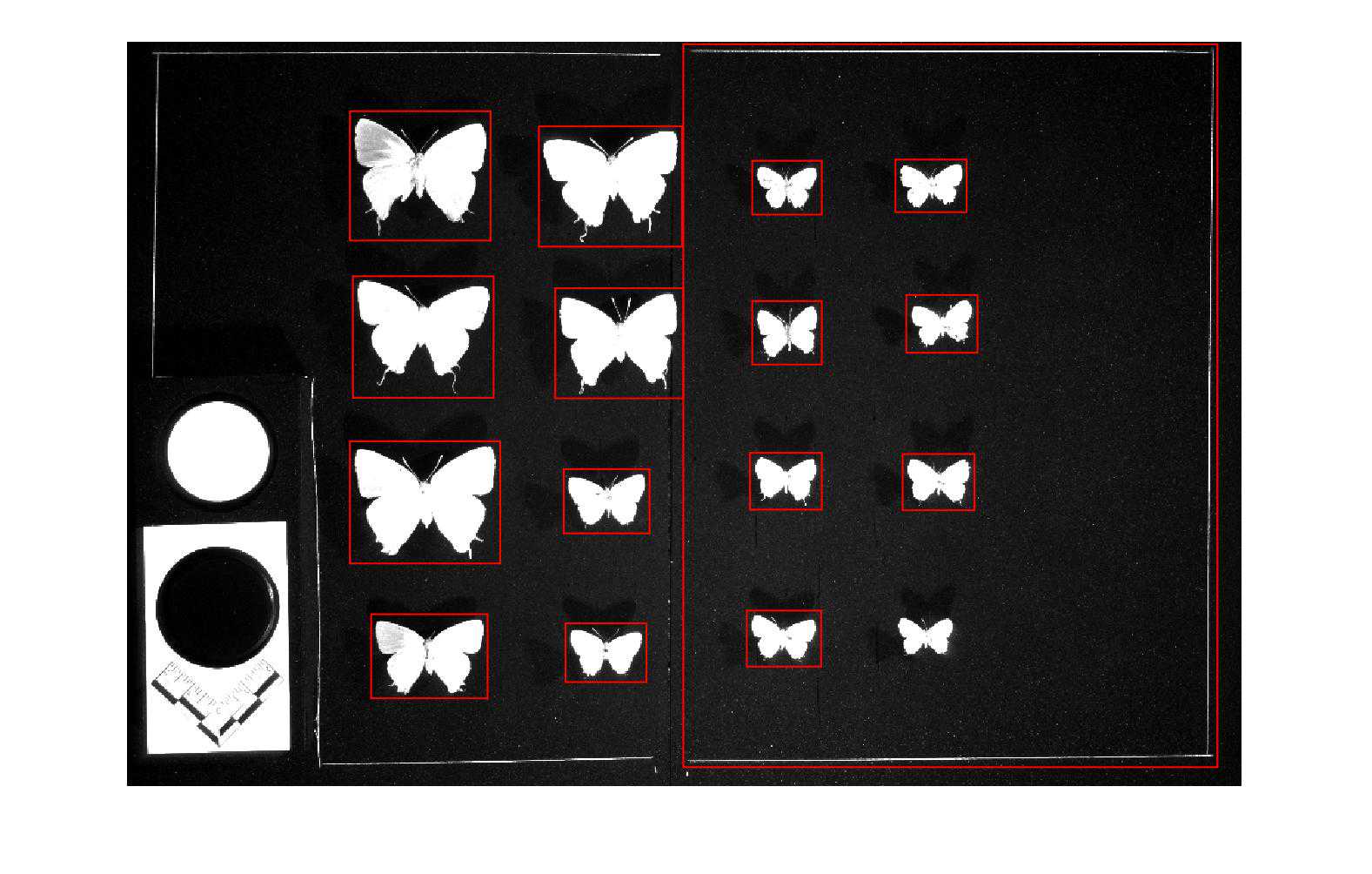
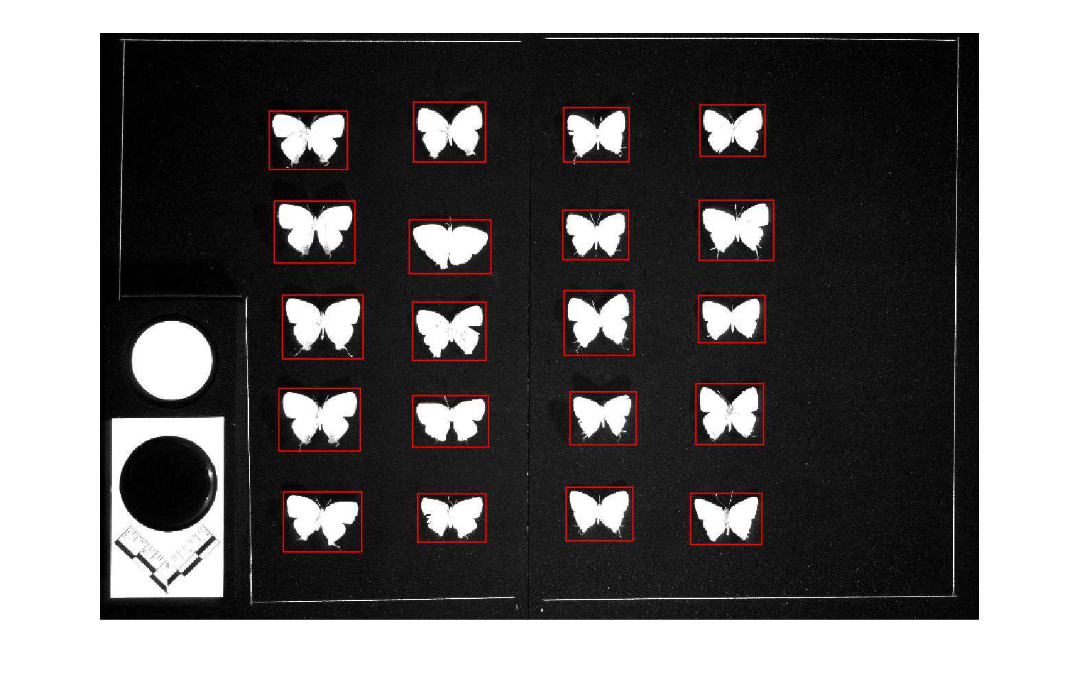
As the algorithm used to identify and create cropping boxes around individual specimens in each drawer image is bound to make some mistakes, manual human inspection is required to identify and correct those errors before downstream image processing may continue. Below are given criteria for identifying problematic boundary boxing errors along with illustrative examples of common boxing errors (Fig. 1 ) and an acceptable drawer image (Fig. 2 ).
An image should be regarded problematic if:
- A specimen lacks a bounding box
- A box encloses more than one specimen
- A box does not completely enclose or inappropriately crops out part of a specimen Multiple boxes enclose one or multiple specimens
We suggest either of two methods for manual inspection: one uses the file managing system native to your computer's OS to preview and sort through image files, whereas the other streamlines the process using Bridge, a file-managing interface by Adobe. Both of these methods are outlined below, the second of which (employing Adobe Bridge) is more time-efficient and highly recommended if processing many image files at once.
Create a folder titled "problematic" within that containing the .jpg files for inspection. This will be used to house all images with specimen boxing errors.
-
Manual drawer inspection using the native file managing system on your local machine:
- Previewing .jpg thumbnails as "large icons," simply navigate through all drawer images in the folder, making sure that all meet the proper criteria for successful specimen boxing (see description and examples above).
- If any drawer images are problematic, move them into the "problematic" folder
- Manual drawer inspection using Adobe Bridge
- Open Adobe Bridge and navigate to the folder containing the .jpg images for manual inspection
- Using the large preview pane in Bridge, navigate sequentially through the images in the folder
- Flag any problematic drawer images using the Bridge "label" feature (keyboard shortcut: Cmd (Mac) / Ctrl (Win) + 6-9)
- Filter for and select "labeled" files only. Move labeled images to the "problematic" folder ( PROBLEMATIC_DIR )
Generate a list of problematic image file names using any available script. The text format in the file should look the same as follows. (They are corresponding to the image name, but the tails indicating wavelength bands were removed.)
Upload the list of problematic drawer images to the cluster and convert to UNIX system format by running dos2unix
#dos2unix
dos2unix PROBLEM_LIST.TXT
Prepare drawer images for manual correction
#prepare drawer images for manual correction
sbatch prepare_files_for_manual_analysis.sh PROBLEM_LIST_DIR PROBLEM_LIST 940 TIFF_IMG_DIR/done TIFF_IMG_DIR MANUAL_DRAWER_CORRECTION_DIR
```(All variables in CAPITAL LETTERS should be specified by the user)

 **PROBLEM_LIST_DIR:**  directory containing the text file list of problematic image filenames (generated in step  **4.3** )


 **PROBLEM_LIST:**  name of the list of problematic images


 **TIFF_IMG_DIR:**  directory containing the drawer images in .tiff format (output of  **3.5** ). These images were moved into an automatically-created folder named "done" within this directory upon completion of the all_in_one_image_analysis script.


* Note: those drawer files named in the problematic_list will be moved out of the "done" folder by this script into the directory specified here. This is to prepare for the rerun of image analysis (following manual corrections) using batch_image_analysis.sh (step  **4.12** ), which will rerun image analysis on all image files matching the names of those in this tiff directory (outside of the "done" folder); thus, it is essential that all files, once transferred from the "done" directory, remain untouched. All files will be retransferred to the "done" folder following completion of batch_image_analysis in downstream steps.
 **MANUAL_DRAWER_CORRECTION_DIR:**  cluster directory into which 940-band problematic .tiff drawer images will be copied for manual processing in later steps. Only the 940-band images are used as they provide a high degree of contrast between specimens and the dark background which ensures both ease and accuracy during the manual partitioning of specimens.
Download the following 3 components to the local machine to proceed with manual bounding box correction:
- .tiff images found in MANUAL_DRAWER_CORRECTION_DIR . Note: this may take some time and requires adequate disc space as the image files are rather large.
- Corresponding bounding box parameters in the manual_boxes directory, found within MATLAB_CODE_LIBRARY : these are MatLab matrices (.mat) prefixed with the names of drawers analyzed .
- Manual bounding box correction tools from Github (https://github.com/weipingchan/Drawer_img_manual_define_bounding_boxes).
Create a folder to organize materials for manual bounding box correction on the local machine. Suggested folder architecture is provided below, and will be referenced as such in subsequent steps of this protocol. Various folders and subfolders are defined below.
manual_drawer_correction
├── 940_tiffs_for_correction
│   ├── done
│   ├── Drawer_1_dorsal.tiff
│   ├── Drawer_1_ventral.tiff
│   ├── Drawer_2_dorsal.tiff
│   ├── Drawer_2_ventral.tiff
│   ├── ...
├── matlab_code_library
│   ├── manual_boxes
│   ├── label_file.csv
│   ├── import_img.m
│   ├── manually_def_with_record.m
│   ├── manually_def_without_record.m
│   ├── ManuallyBoxDefine.m
│   ├── ManuallyFindCoraseOutlines2.m
│   ├── README.md
|_
``` **940_tiffs_for_correction:** contains .tiff files needing correction which have been downloaded from the cluster. During the correcting process, manually corrected .tiffs will be moved into the  **done** subfolder also created within this local folder.


 **matlab_code_library:** houses the following three components needed for manual correction:


1. **manual_boxes:** MatLab bounding box parameters corresponding to each downloaded .tiff file (which was copied from the cluster). Note that this folder  _must_ be placed in the matlab_code_library along with the MatLab package files in order for the manual correction protocol to run smoothly
1. **label CSV file**  (as described in  **3.1** )
1. **MatLab package files** for manual correction from Github
Open Matlab and run the script ManualBoxDefine.m
Specify paths in script header prior to running:
Img_directory ='path_to/940_tiffs_for_correction'; %path to .tiff-containing directory
Code_directory='path_to/matlab_code_library'; %The path to the MATLAB script library
Result_directory='path_to/results'; %Directory to which the results of correction should be written
labelfileName='label_file.csv'; %The corresponding CSV file that containing label information (see Examplar file for data structure in section 3.1)
Note: requires user to have or install 'struct2dataset' package in the Statistics and Machine Learning Toolbox for MatLab
Guide to using the manual box-bounding interface:
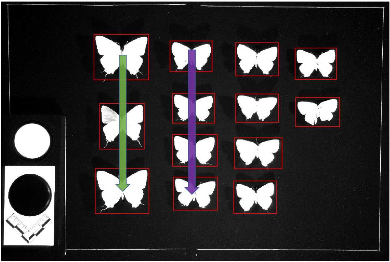
The program will cycle through specimens in top-to-bottom, left-to-right order (see drawer schematic in 3.1) and ask you to confirm the bounding box of each one individually or adjust if errors are present 3.1 ) and ask you to confirm the bounding box of each one individually or adjust if errors are present
- A window displaying a problematic drawer image will be opened automatically by the program
- Press the "down" arrow TWICE to confirm a specimen's bounding box and move on to the next
- If the bounding box shown for a given specimen appears problematic, press the "left" and "right" arrow keys to move through box options and select the preferred bounding box. Confirm the selection and move on by pressing TWICE the "down" arrow key
- Alternatively, drag a bounding box from a similarly-sized adjacent specimen over a specimen that appears to have been skipped (use "left" and "right" to view and select)
- Use the cursor to resize a box if needed by dragging the edges of the red outline
- Press "r" if you want to redo this entire image before it is closed
- Press 'f' if you want to finish the process or if the panel doesn't close by itself (i.e. No corresponding record found.) after defining the box for the last specimen on the stage. (Must do it right after defining the last one! [pressing twice the "down arrow" for the last one.])
Specimen outline inspection and manual correction
This process resembles step 4 (drawer inspection and correction) in many of its steps and aspects; however, there are some salient procedural differences 4 (drawer inspection and correction) in many of its steps and aspects; however, there are some salient procedural differences that warrant the detailed, though at times redundant, protocol description below.
Download all .jpg files in the spp_inspection directory (under [ RESULT_DIRECTORY]/Drawer_result ) from the cluster to a folder on your local machine. As outlined in 3.5 , these image files should be named accordingly: "[specimen_ID]_[dorsal/ventral]_940_demo.jpg"
Note: some files generated from previously problematic drawers during the first round of batch_image_analysis will be prefixed with "TempLabel." These may be deleted post-manual drawer correction (section 4) so as not to conserve duplicates
Copy the images with redefined masks (*.tiff) to the cluster
Upload those .tiff files to the cloud drive and use rclone to clone them to the cluster, or -- as mentioned previously in 5.8 -- simply use SSH/FTP software to upload the .tiffs directly from your local machine.
Run batch_update_manually_remasked_spp.sh to update matrices for manually corrected images
#batch_update_manually_remasked_spp.sh
sbatch batch_update_manually_remasked_spp.sh REMASKED_TIFF_DIR SPP_MATRICES_REMASK_DIR/done_matrices MATLAB_CODE_LIBRARY CORRECTED_MATRICES_SAVE_DIR
``` **REMASKED_TIFF_DIR:**  directory containing manually remasked specimen image files (.tiff)


 **SPP_MATRICES_REMASK_DIR/done_matrices:**  directory containing matrices previously extracted for remasking (see  **5.7** )


 **CORRECTED_MATRICES_SAVE_DIR:**  directory to which the program should save corrected MatLab matrices
Copy all original spp_matrices under Drawer_result to a new directory named ' final_spp_matrices '.
Copy updated (remasked) matrices from their directory ( CORRECTED_MATRICES_SAVE_DIR ) to final_spp_matrices, overwriting those outdated ones. Now we have a final specimen matrix database.
For copying files, a simple 'cp -r' command or 'rclone' should both work. If one wants to submit a bash script, the following bash script may be useful:
#copy_spp_matrices_to_somewhere.sh
sbatch copy_spp_matrices_to_somewhere.sh ORIGIN DESTINATION
``` **ORIGIN** : the directory containing specimen matrices (*AllBandsMask.mat)


 **DESTINATION** : the destination to which those files will be copied
Manually inspect and flag individual specimens for specimen outline errors using either the local machine's native image previewing system or Adobe Bridge (methods outlined in 4.2 ). Move problematic images into a separate subfolder named "problematic" ( PROBLEMATIC_DIR ). For guidelines regarding how to evaluate specimen boundaries, see the Image Criteria section of the Manual for Specimen Inspection and Correction)
Generate a list of problematic specimen files to extract (using a script like that used in step 4.3 to do the same for problematic drawer files). The text format in the file should look the same as follows. (They are named according to specimen name, but the tails indicating wavelength bands were removed.)
inspectionDir =
  "PROBLEMATIC_DIR";
imglist = FileNames["*.jpg", inspectionDir];
problemlist =
  Join[Table[
    StringSplit[StringSplit[imglist[[n]], "\\"][[-1]],
      "_940_demo.jpg"][[1]], {n, 1 , Length[imglist]}], {""}];
outname =
  inspectionDir <> "\\" <>
   StringSplit[StringSplit[imglist[[1]], "\\"][[-3]],
     "_spp_inspection"][[1]] <> "_problem_list-" <>
   FileNameSplit[inspectionDir][[-1]] <> ".txt";
Export[outname, problemlist, "List"];
MatrixForm[problemlist]
```The above Mathematica script takes one input (the path of the problematic specimen image directory; under  **PROBLEMATIC_DIR** )  _Note: Mathematica path hashes take the form "\\"_


The resulting problematic_spp_list.txt file will be written to the PROBLEMATIC_DIR
Transfer the list of problematic specimen images to the cluster and convert to UNIX format using the command:
dos2unix [list_file]
Create a series of directories on the cluster to organize files for manual correction as they are pulled using the list of problematic images generated in step 5.3 . Suggested directory architecture is specified below:
spp_manual_correction
└── spp_matrices_history
    ├── spp_matrices_remask
    └── spp_matrices_remask_tiff
``` **spp_matrices_remask:** MatLab matrices (.ma) specifying boundary-drawing parameters for each problematic image specified in the problematic_list.txt will be copied here (see  **5.6** )


 **spp_matrices_remask_tiff:** TIFF images of problematic specimens will be copied here (see  **5.7** ).
Extract specimen MatLab matrices according to the filenames specified in the list of problematic images.
#copy_spp_matrices_according_to_list.sh
sbatch copy_spp_matrices_according_to_list.sh PROBLEM_LIST_DIR PROBLEM_LIST_NAME SPP_MATRICES_DIR/ SPP_MATRICES_REMASK_DIR
(All variables in CAPITAL LETTERS should be specified by the user)
PROBLEM_LIST_DIR : directory housing the problematic_spp_list.txt specifying filenames to be pulled
PROBLEM_LIST_NAME : .txt file specifying the filenames of specimens whose boundaries were misdrawn by the algorithm and classified as "problematic" upon inspection (generated in step 5.3 )
SPP_MATRICES_DIR : Directory containing MatLab specimen boundary parameters for every specimen imaged. Located and created in the RESULT_DIRECTORY during all_in_one_image_analysis (see 3.5 ) [note: the directory name must be followed by a '/' in order for the files to be correctly sourced from the folder
SPP_MATRICES_REMASK_DIR : Directory to which problematic matrices will be copied (see previous step)
Extract TIFF files for manual correction.
#batch_matrices_to_shp_correction_tiff.sh
sbatch batch_matrices_to_shp_correction_tiff.sh SPP_MATRICES_REMASK_DIR MATLAB_CODE_LIBRARY SPP_TIFF_REMASK_DIR
(All variables in CAPITAL LETTERS should be specified by the user)
SPP_MATRICES_REMASK_DIR : Directory to which problematic matrices were copied (see previous two steps)
SPP_TIFF_REMASK_DIR : Directory to which problematic TIFFs corresponding to matrices in SPP_MATRICES_REMASK_DIR will be copied (see step 5.5 )
Note: problematic TIFFs for manual correction are pulled and copied by the script according to the filenames of matrices in SPP_MATRICES_REMASK_DIR (pulled in previous step). Thus, it is important that matrix files are not renamed or moved into a subdirectory prior to running the above script. Matrices will automatically be moved to an autogenerated subdirectory within SPP_MATRICES_REMASK_DIR ("done_matrices") once their corresponding TIFFs have been copied.
Use rclone to upload the spp_manual_correction folder from the cluster to the cloud. You can then download them to your local machine.
(Direct download from the cluster to local disk is also fine, but the large file transportation requires a stable internet connection. A secure SSH/FTP server such as Bitvise is advised for file management directly between the cluster and a local machine.)
Use Adobe Photoshop or GIMP to adjust the mask belonging to each problematic image. Instructions and guidelines for manual mask correction are specified in the Manual for Specimen Inspection and Correction.
Manual fore- and hindwing segmentation
run batch_matrices_to_beautiful_RGB.sh to generate .jpg images for fore-hindwing segmentation.
#batch_matrices_to_beautiful_RGB.sh
sbatch batch_matrices_to_beautiful_RGB.sh SPP_MATRICES_DIR MATLAB_CODE_LIBRARY RESULT_DIR REMOVE_BACKGROUND IMG_EXTENSION RESOLUTION
SPP_MATRICES_DIR: Directory containing all finalized/manually checked and corrected specimen image matrices
MATLAB_CODE_LIBRARY: Directory containing MatLab program files
RESULT_DIR: Directory in which the output images should be placed
REMOVE_BACKGROUND: Remove background according to the mask (0: no background removal; 1: background removal; for fore-hindwing segmentation, 0 is suggested)
IMG_EXTENSION: Image format (e.g. jpg, png, pdf, etc... 'jpg' is suggested for the fore-hindwing segmentation)
RESOLUTION: Resolution of the output images. (e.g. 150 [dpi]; decent resolution [>=150] is suggested for the fore-hindwing segmentation. However, higher resolution means larger image size)
Copy newly generated .jpg images in RESULT_DIR from the cluster to the local disk
Set up aworking environment for fore-hindwing segmentation and begin the segmentation by following the rules listed in the tutorial document & video.
Upload the .json files in the folder named 'segmented ' to the cluster
Download the MatLab scripts from the GitHub repository to another MatLab code library to prevent potential conflict .
Run the shape analysis script to segment the specimens
#shape analysis script
sbatch batch_morph_preprocessing.sh SPP_MATRICES_DIR MATLAB_CODE_LIBRARY JSON_DIR RESULT_DIR SPHINGIDAE
``` **SPP_MATRICES_DIR:**  Directory containing all finalized/manually checked and corrected specimen image matrices (note: do not include '/' at the end of the path)


 **MATLAB_CODE_LIBRARY**


 **JSON_DIR** : Directory containing .json files created during manual wing segmentation. Found in folder named 'segmented' and uploaded to the cluster in step  **6.4**


 **RESULT_DIR** : Directory to which segmentation results should be written


 **SPHINGIDAE** : (Options: 0,1) If the pre-posed-wing image is desired desperately for Sphingidae-like specimens, manually change this to 1. Please note that the resulting Sphingidae shape analyses may be very error-prone.
Landmarks inspection and manual correction
Download the images in Shape_analysis/wing_segmentation to local disk
Copy the output folder ( *\Shape_analysis ) to the cluster
Update the original shape results with manually corrected ones.
#update_shape_analysis_folder.sh
sbatch update_shape_analysis_folder.sh UPLOADED_SHAPE_ANALYSIS_DIR ORIGINAL_SHAPE_ANALYSIS_DIR
``` **UPLOADED_SHAPE_ANALYSIS_DIR** : shape analysis folder containing manually corrected results


 **ORIGINAL_SHAPE_ANALYSIS_DIR:** shape analysis folder generated in  **7**
Use Adobe Bridge to do the inspection and put problematic ones into a subfolder labeled "problematic"
Generate a list of problematic specimen names and upload the list to the cluster.
Convert the PROLEM_LIST to UNIX format using the command
dos2unix [list_file]
First, run copy_files_according_to_list.sh to copy morph-seg.mat files corresponding to those specimens in the list of problematic images generated above (step 8.3 ) to a new, separate directory.
Then, copy this directory containing problematic matrices (*morph-seg.mat) to the local disk.
#copy_files_according_to_list.sh
sbatch copy_files_according_to_list.sh PROBLEM_LIST_DIR PROBLEM_LIST_NAME morph-seg.mat */Shape_analysis/wing_shape_matrices-seg/ DESTINATION_DIRECTORY
``` **PROBLEM_LIST_DIR** : directory in which the list of problematic specimens resides on the cluster


 **PROBLEM_LIST_NAME** : name of the .txt file listing all problematic specimens


 **MORPH-SEG_DIR:** Directory containing all morph-seg.mat matrices, which describing detailed segmentation information. It's usually in the following path '*/Shape_analysis/wing_shape_matrices-seg/'


 **DESTINATION_DIRECTORY**
Copy json files (*.json) to the local disk.
(Note: These files may already be in a directory on your local disk if using the same machine used to manually segment specimens -- see Step 6.3 )
Download the required script here, and check if all necessary MatLab toolboxes are installed properly according to the list below:
Open MatLab and open the script named: manually_calculate_morph.mSpecify the required arguments and paths in the heading and run the script.Arguments & paths for specification [in the script header]:``` Code_directory=''; %Directory in which MATLAB morphometric segmentation scripts live morph_mat_directory=''; %Directory of morph-seg.mat files pulled for problematic images; It can also be the dir of allBandsMask.mat spp_json_directory=''; %Directory of JSON files created during manual wing segmentation process Result_directory=''; %Directory to which you would like to write shape analysis results addpath(genpath(Code_directory)) %Add the library to the path SphingidaeOrNot=0; %If the pre-posed-wing image is desired desperately for Sphingidae-like specimens, manually change this to 1. Please note that the resulting Sphingidae shape analyses may be very error-prone. antTrimPx=10; %Adjust this to extract bold antenna if necessary (20-30 for big antenna; 5-10 for thin antenna; <5 for tiny specimens) jumboAntenna=0; % set to 1 for the jumbo antenna which have multiple forks (jumbo mode will dilate a little to remove those forks)
Manually correct shape landmarks. See the following quick guide:
Using the cursor, click and drag misidentified landmarks (red points) to the desired location.
Plot order moves in a clockwise manner around the specimen image, identifying morphometric landmarks in the following order:
- Left corner dividing Fore & Hing Wings
- Left corner dividing Forewing & Body
- Right corner dividing Forewing & Body
- Right corner dividing Fore & Hing Wings
- Right corner dividing Hindwing & Body
- Left corner dividing Hindwing & Body
- Left forewing tip
- Right forewing tip
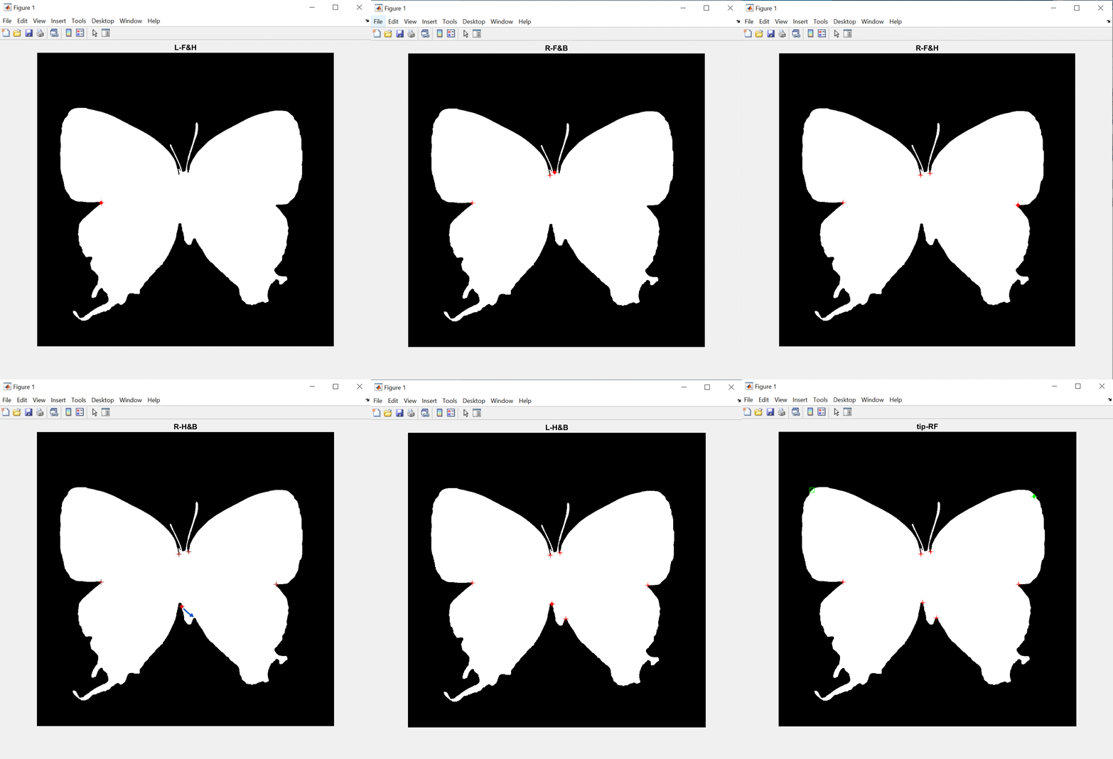
Press ENTER to confirm using the point shown on the screen. This will also move the correction process forward to the next landmark.
Press 'r' to redo the manual process
Press 'f' to force-exit the entire manual process
Note: once ENTER is pressed, the point will move to the nearest detected white/black edge boundary; for precise and rapid point placement, merely re-position landmark points just close enough to the desired location to enable the program to automatically detect the correct and nearest edge at which to place the landmark.
For all images, matrices, and results, change owner or open permission for group members
#Change directory & file permissions
chmod -R 754 */Shape_analysis

