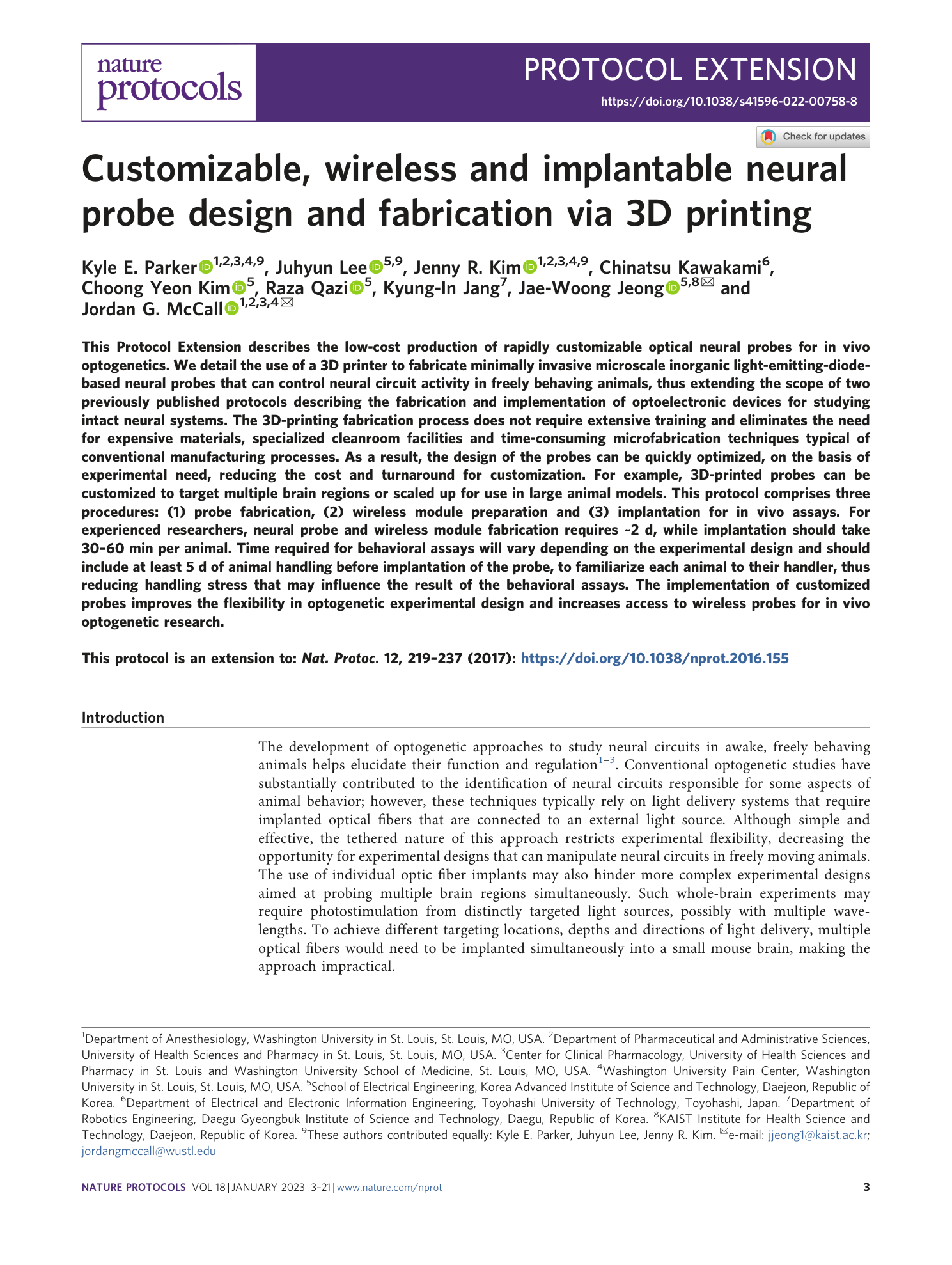
Customizable, wireless and implantable neural probe design and fabrication via 3D printing
Kyle E. Parker, Juhyun Lee, Jenny R. Kim, Chinatsu Kawakami, Choong Yeon Kim, Raza Qazi, Kyung-In Jang, Jae-Woong Jeong, Jordan G. McCall
Extended
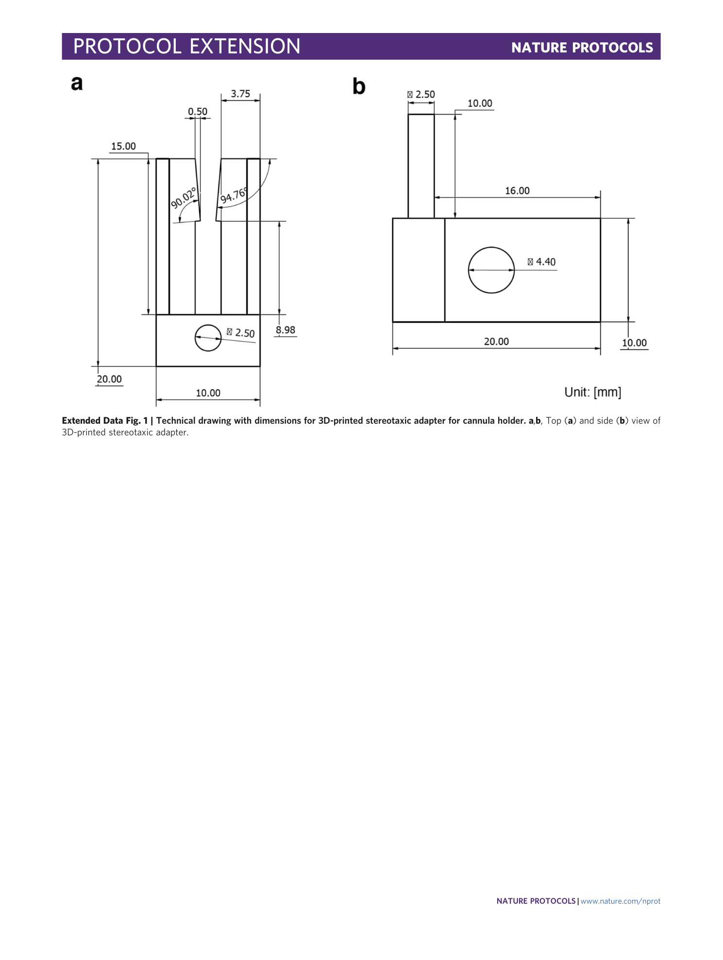
Extended Data Fig. 1 Technical drawing with dimensions for 3D-printed stereotaxic adapter for cannula holder.
a , b , Top ( a ) and side ( b ) view of 3D-printed stereotaxic adapter.
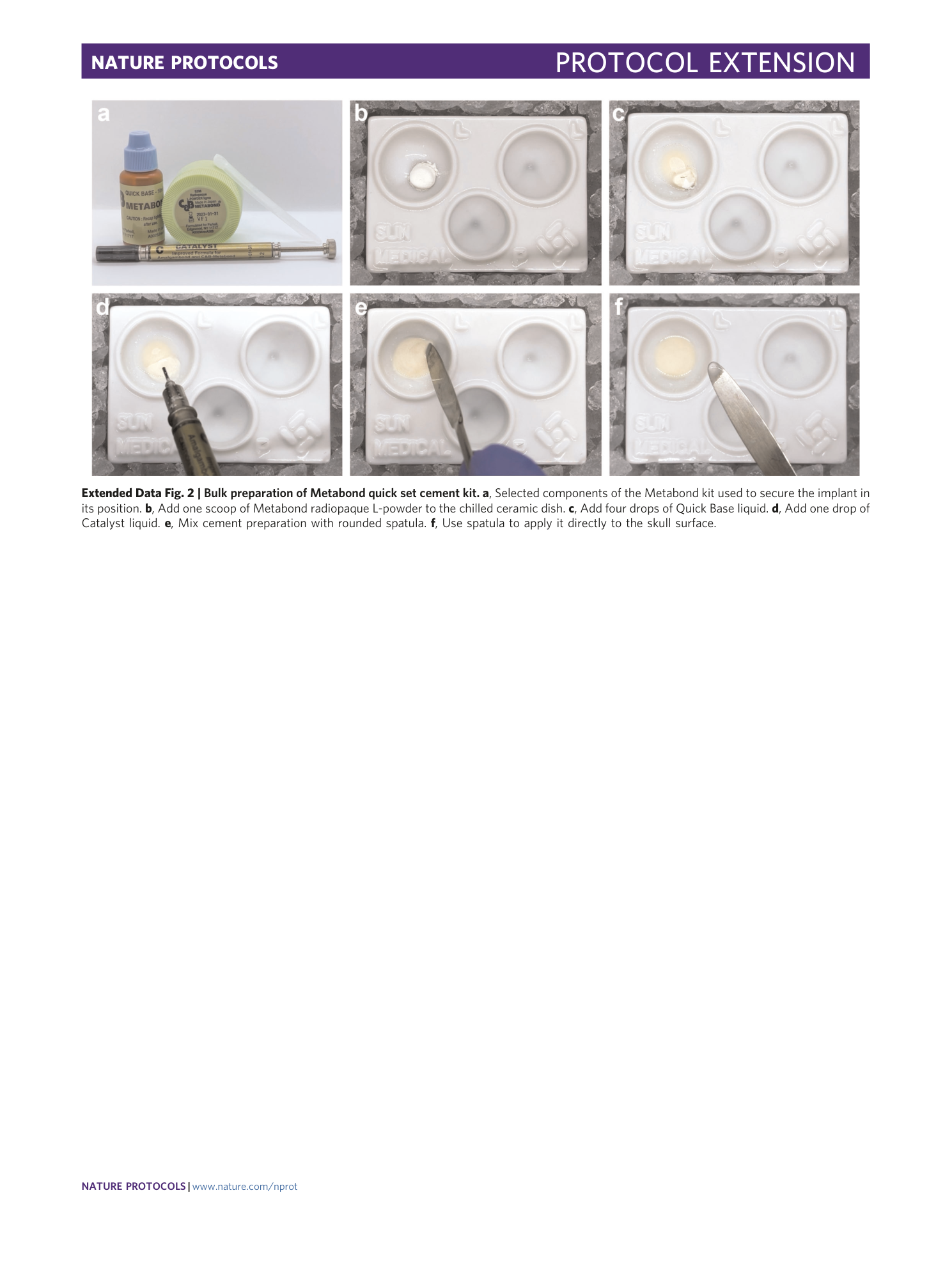
Extended Data Fig. 2 Bulk preparation of Metabond quick set cement kit.
a , Selected components of the Metabond kit used to secure the implant in its position. b , Add one scoop of Metabond radiopaque L-powder to the chilled ceramic dish. c , Add four drops of Quick Base liquid. d , Add one drop of Catalyst liquid. e , Mix cement preparation with rounded spatula. f , Use spatula to apply it directly to the skull surface.
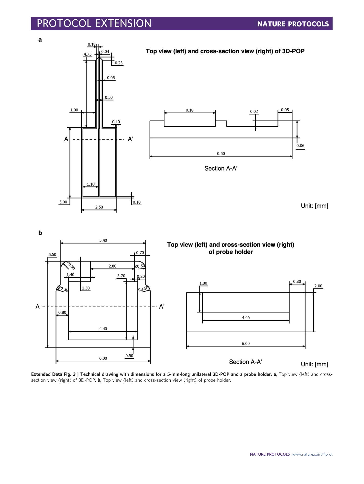
Extended Data Fig. 3 Technical drawing with dimensions for a 5-mm-long unilateral 3D-POP and a probe holder.
a , Top view (left) and cross-section view (right) of 3D-POP. b , Top view (left) and cross-section view (right) of probe holder.
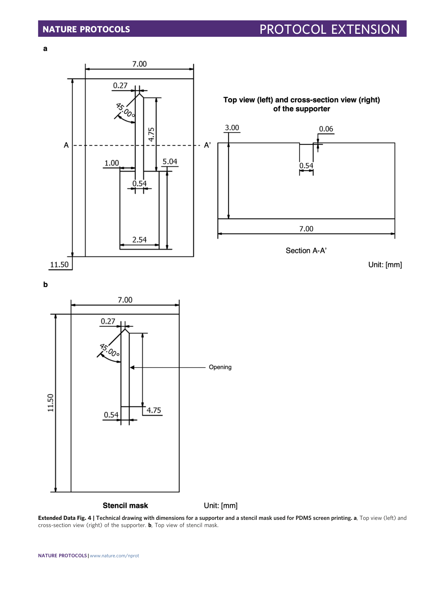
Extended Data Fig. 4 Technical drawing with dimensions for a supporter and a stencil mask used for PDMS screen printing.
a , Top view (left) and cross-section view (right) of the supporter. b , Top view of stencil mask.
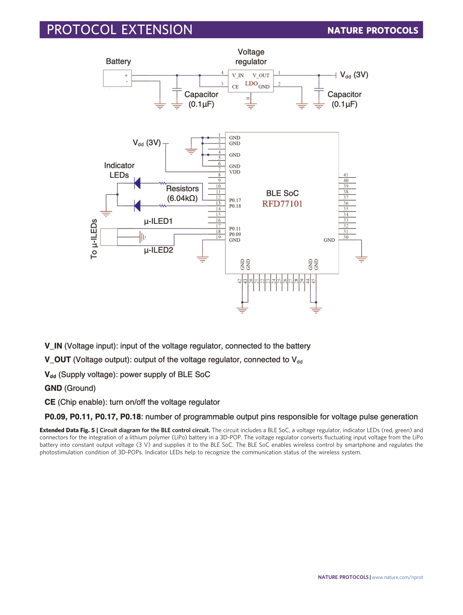
Extended Data Fig. 5 Circuit diagram for the BLE control circuit.
The circuit includes a BLE SoC, a voltage regulator, indicator LEDs (red, green) and connectors for the integration of a lithium polymer (LiPo) battery in a 3D-POP. The voltage regulator converts fluctuating input voltage from the LiPo battery into constant output voltage (3 V) and supplies it to the BLE SoC. The BLE SoC enables wireless control by smartphone and regulates the photostimulation condition of 3D-POPs. Indicator LEDs help to recognize the communication status of the wireless system.
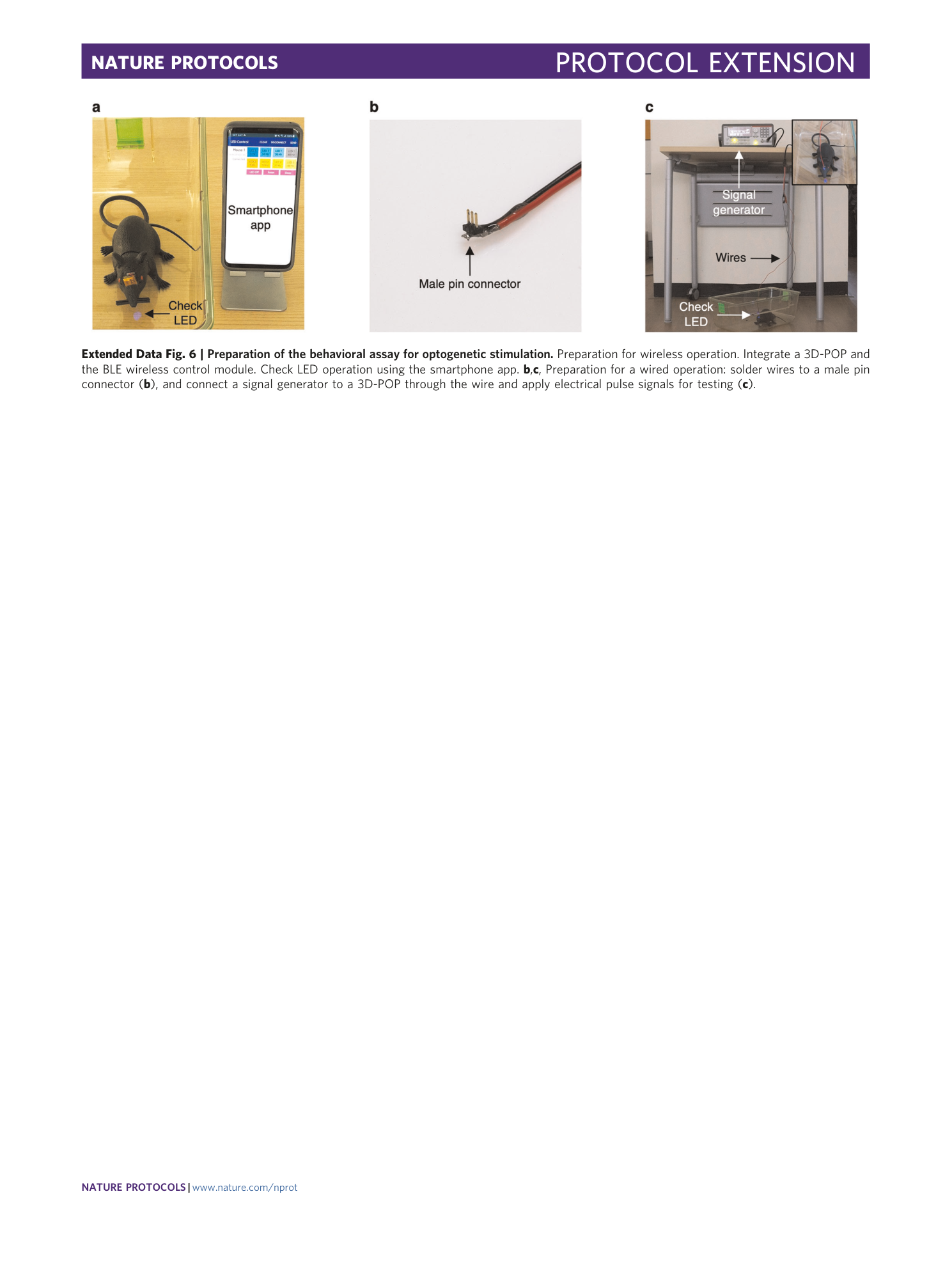
Extended Data Fig. 6 Preparation of the behavioral assay for optogenetic stimulation.
Preparation for wireless operation. Integrate a 3D-POP and the BLE wireless control module. Check LED operation using the smartphone app. b , c , Preparation for a wired operation: solder wires to a male pin connector ( b ), and connect a signal generator to a 3D-POP through the wire and apply electrical pulse signals for testing ( c ).
Supplementary information
Supplementary Data 1
STL file for the stereotaxic adapter
Supplementary Data 2
STL files for the 1D probe
Supplementary Data 3
STL files for PDMS screen printing
Supplementary Data 4
Gerber and CAD files for the wireless control circuit
Supplementary Data 5
Program code for the BLE SoC
Supplementary Data 6
Source codes for the smartphone application
Supplementary Data 7
STL files for the 3 × 3 probe
