DiI Labelling with a Paintbrush: a Low-cost Alternative to DiOlistic Labelling in Neurons
Stephanie J. Huang, Joyce Colussi-Mas, Bart A. Ellenbroek
Abstract
DiOlistic labelling is a high-throughput technique commonly used to label neurons in fixed brain tissue using the fluorescent lipophilic carbocyanine dye, DiI. It labels a large population of neurons in a dense yet distributed pattern, making it ideal for morphological studies. However, DiOlistic labelling typically requires an expensive commercial gene gun. Therefore, our protocol presents a low-cost alternative using materials that are already available in most laboratories (e.g. a plastic 12-well culture plate lid) or easily acquired at a low price (e.g. a paintbrush). We detail the DiI labelling process, including the preparation, delivery, incubation, and post-processing steps. Overall, this protocol labels a large population of neurons in a dense yet distributed pattern and, therefore, is a simple and low-cost alternative to DiOlistic labelling.
Before start
See the guidelines section.
Steps
DiI Preparation
Combine the following in a falcon tube.
6mgof DiI crystals40mLof 100% Ethanol
Vortex the solution intermittently for several minutes until no clumps remain.
Storage - Decant the prepared DiI solution into a dark/amber glass bottle, seal it, and wrap it with foil to protect it from light. Then, store the bottle at 4°C until further use.
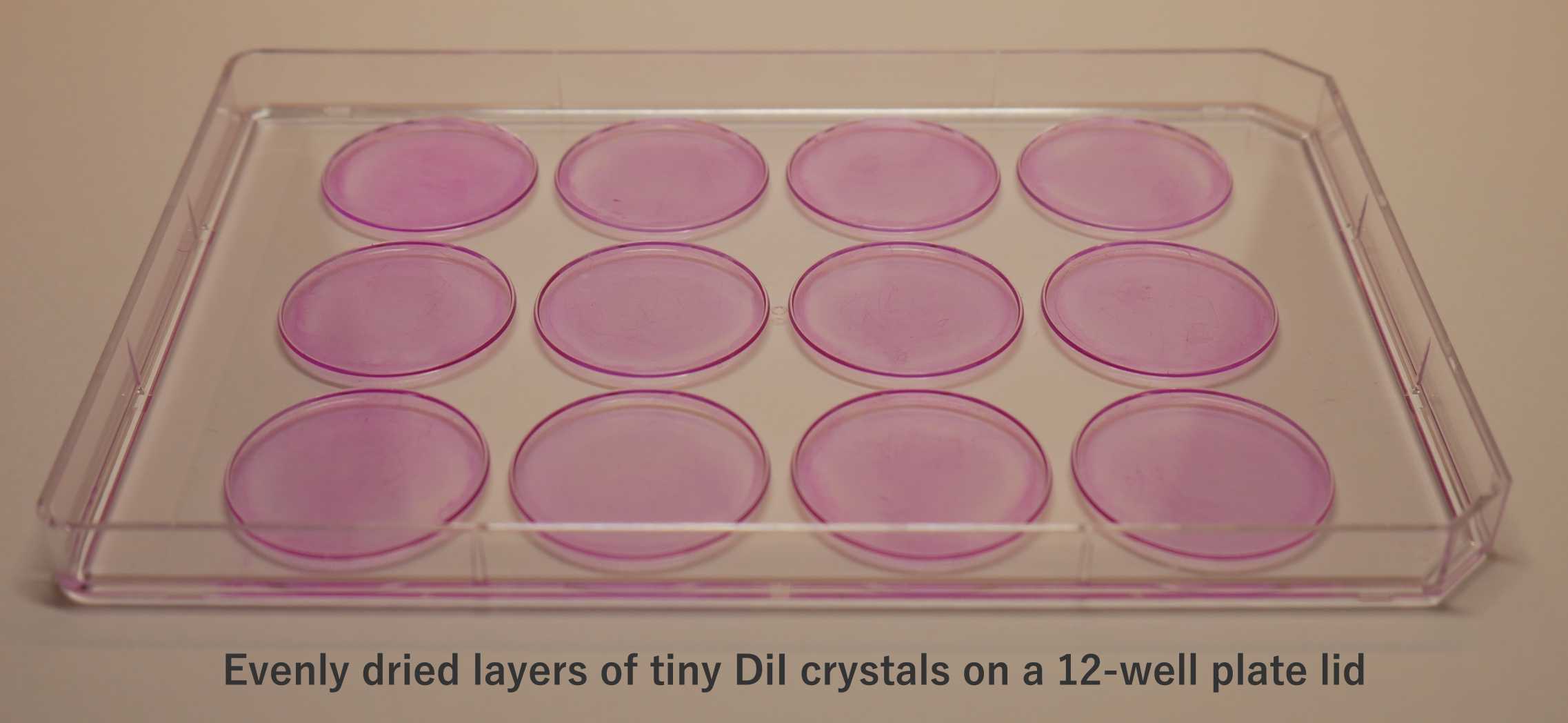
Prepare the DiI-coated well plate lids (150µL of stock solution per well lid ∴ ~0.0225mg of DiI per well).

Place a clean, dry lid of a 12-well plate onto a flat surface (interior facing upwards).
Briefly vortex the DiI solution & pipette 150µLonto each well lid. Make sure the DiI solution does not go over the ledge/condensation rings of the well lid.
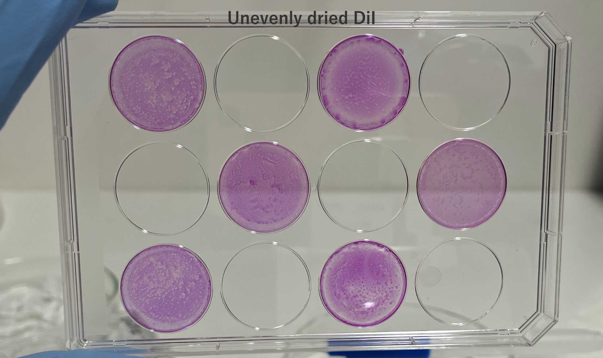
Leave to dry overnight on a flat surface in the dark (e.g., in a fumehood or on a bench in a dry room). Avoid disturbing the plate whilst drying; otherwise, it will become uneven.
Room temperature
Storage - Clasp the dried DiI-coated well plate lid onto the accompanying well plate, wrap it in foil, and store it in a dry, dark cupboard or drawer atRoom temperature until further use (use within 2 weeks).
DiI Delivery

See the video demonstration & refer to the timestamps in the description bar.
#尊敬的用户,由于网络监管政策的限制,部分内容暂时无法在本网站直接浏览。我们已经为您准备了相关原始数据和链接,感谢您的理解与支持。
<iframe title="YouTube video player" src="https://www.youtube.com/embed/LtF5g5fkxdM?si=Yvl4wQZtgHyToDbx" height="315" width="560"></iframe>
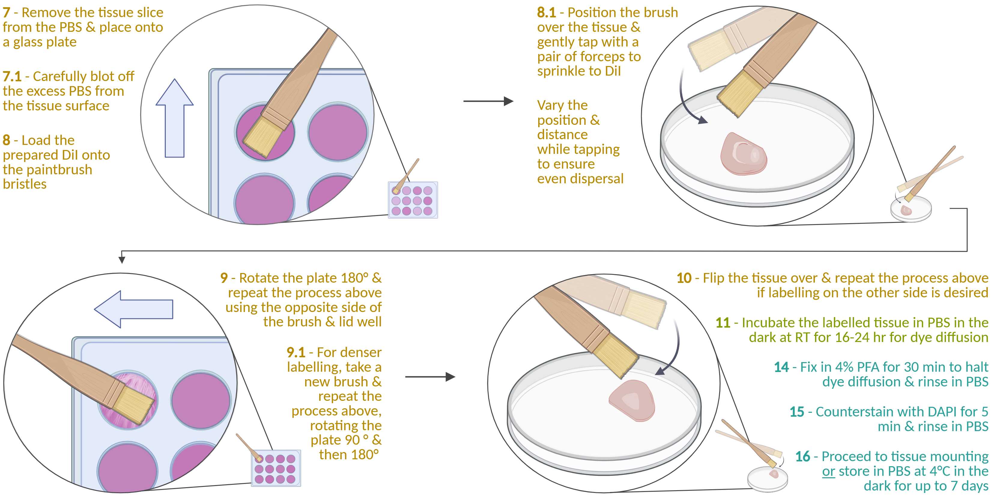
Remove the fixed tissue slice from the PBS and place it onto a clean, dry surface (e.g., a glass petri dish or a well plate lid).
Using a pair of metal forceps, take a small piece of a shredded Kimwipe and carefully blot the excess PBS from the tissue surface via capillary action. Hold the glass dish and tilt it towards yourself to aid in drawing the liquid away. Avoid directly blotting over the region of interest and overdrying it.
Take a paintbrush (see materials section & the note below for more information) and load the DiI onto one side of the bristle tips by dragging them across half a DiI well lid in a short, smooth stroke. Try to apply even pressure across the bristles and avoid the edges/condensation ring of the well lid.
Position the paintbrush parallel to the tissue slice, about 2 cm above it, with the bristle tips aligned with the slice's top edge. Use a pair of metal forceps to gently tap the brush's ferrule, dislodging and sprinkling DiI onto the tissue. Between taps, move the brush forward and backward for even dispersion (tap for ~10 s).
Next, vary the brush angle and distance (e.g., hold it perpendicular to the slice) and tap more firmly to dislodge the remaining DiI (tap for ~5 s).
Rotate the plate 180º. Flip over the paintbrush and drag the unused side of the bristles onto the unused half of the DiI-coated well lid as described in step 8 . Then repeat steps 8.1 and 8.2 (this will be DiI delivery to edge 2 - see figure 6).
For more coverage, rotate the slice 90º and then 180º, repeating steps 8, 8.1, and 8.2 (this will be DiI delivery to edges 3 and 4 - see figure 6). Before doing so, either use a new brush or clean the brush by wiping the bristles on a clean Kimwipe and tapping to remove the excess DiI (this is to prevent clumping).


OPTIONAL: LABELLING THE OPPOSITE SIDE OF THE TISSUE OPTIONAL: LABELLING THE OPPOSITE SIDE OF THE TISSUE
Repeat on the other side if desired, but make sure to re-moisten the tissue slice with PBS before picking it up. Also, make sure to flip it over onto a clean section of the glass plate to avoid picking up DiI crumbs dropped from the previous steps.
DiI Incubation
Return the tissue slice to the PBS in the 12-well plate. Cover and incubate for 16-24 h at RT in the dark to allow the dye to diffuse along the neuronal arbours. 20h 0m 0s Room temperature
OPTIONAL: CHECKING THE DENSITY OF LABELLING OPTIONAL: CHECKING THE DENSITY OF LABELLING (1-2 h after DiI delivery)
Carefully remove the labelled slice and mount it onto a glass-bottom imaging dish with plenty of PBS to avoid drying whilst viewing. Afterwards, return to the well and resume the incubation process.
- If the labelling is too sparse , the slice can be relabelled by repeating the processes above. However, the additional handling may damage the tissue, so we typically do not relabel.
- Instead, we recommend first becoming proficient with the delivery technique using test samples. Do this by carefully documenting the DiI delivery process and the resulting labelling pattern, then repeating until the desired pattern is consistently obtained. Each time, make small adjustments to the technique and then see how it affects the pattern of neuronal labelling.
- Once mastered, you will be able to perform the DiI delivery with the unaided eye and achieve consistently high-quality labelling. You will not need to perform labelling checks or relabel the tissue.

DiI Post-processing
Bring the following solutions to Room temperature
- 4% PFA
- PBS
- DAPI
Under the fumehood, remove the excess PBS from the well containing the labelled tissue and add 3.5mL of 4% PFA. Incubate for 30 min.
Remove the PFA and rinse twice with PBS (1 min per wash).
Add 400µL DAPI solution to the well. Tilt the plate while incubating to ensure the solution fully covers the tissue (otherwise, use more DAPI solution or use smaller volume well plates, e.g. a 24-well plate).
Remove the DAPI and rinse twice with PBS (5 min per wash).
Either proceed to storage or tissue mounting .
- For storage , place into a well filled with PBS, cover and wrap in foil, and store at 4°C.
- For tissue mounting , refer to the guidelines section for further information.
Cleaning & Maintenance
To clean the paintbrushes , fill a small container with ethanol and dip the DiI-coated bristles into it. Brush against the walls of the container to break up any remaining DiI and drag across a Kimwipe. Repeat this process once, then allow the brush to air-dry for 24 hours before reuse.
To clean a used DiI-coated well plate lid , pour ethanol over it and allow the DiI to dissolve. Wipe the lid clean with a Kimwipe, and repeat if necessary. Then rinse with ddH2O and air-dry before reuse.
Examples
Examples of whole neurons

Examples of dendritic segments
<img src="https://static.yanyin.tech/literature_test/protocol_io_true/protocols.io.dm6gpzjr1lzp/dendrites_v4.png" alt="Figure 10. Examples of dendritic segments. Image stacks were acquired using an Olympus FV3000 CLSM. a) A terminal basal dendritic segment covered in spines & an axon with boutons from a cortical pyramidal neuron. b) Thorny excrescences from a dendritic segment of a hippocampal CA3 pyramidal neuron. b) A terminal apical tuft from a cortical pyramidal neuron densely covered in dendritic spines with complex morphologies. d) Dendritic segments from extremely truncated cortical pyramidal neurons. The arrows indicate the notching. Truncated dendritic segments at the tissue surface often show aberrant notching (& possibly swelling), similar to dendritic varicosities seen after neuronal injury. These truncated surface segments appear to provide "high-quality" image stacks due to intense labelling & less axial blurring compared to the deeper segments from intact neurons. Although tempting to sample, these truncated segments should be avoided as they introduce confounds. All images were acquired with a sampling pixel of 50 nm & z-step of 150 nm using a 60× silicone oil immersion objective lens & then deconvolved in CellSens using either 25 iterations of the fast maximum likelihood algorithm (a) or 20 iterations of the advanced maximum likelihood algorithm with noise reduction (b,c,d). Following deconvolution, the z-series were stacked in ImageJ & presented as greyscale MIP with a 1 & 5 µm scale bar. " loading="lazy" title="Figure 10. Examples of dendritic segments. Image stacks were acquired using an Olympus FV3000 CLSM. a) A terminal basal dendritic segment covered in spines & an axon with boutons from a cortical pyramidal neuron. b) Thorny excrescences from a dendritic segment of a hippocampal CA3 pyramidal neuron. b) A terminal apical tuft from a cortical pyramidal neuron densely covered in dendritic spines with complex morphologies. d) Dendritic segments from extremely truncated cortical pyramidal neurons. The arrows indicate the notching. Truncated dendritic segments at the tissue surface often show aberrant notching (& possibly swelling), similar to dendritic varicosities seen after neuronal injury. These truncated surface segments appear to provide "high-quality" image stacks due to intense labelling & less axial blurring compared to the deeper segments from intact neurons. Although tempting to sample, these truncated segments should be avoided as they introduce confounds. All images were acquired with a sampling pixel of 50 nm & z-step of 150 nm using a 60× silicone oil immersion objective lens & then deconvolved in CellSens using either 25 iterations of the fast maximum likelihood algorithm (a) or 20 iterations of the advanced maximum likelihood algorithm with noise reduction (b,c,d). Following deconvolution, the z-series were stacked in ImageJ & presented as greyscale MIP with a 1 & 5 µm scale bar. "/>
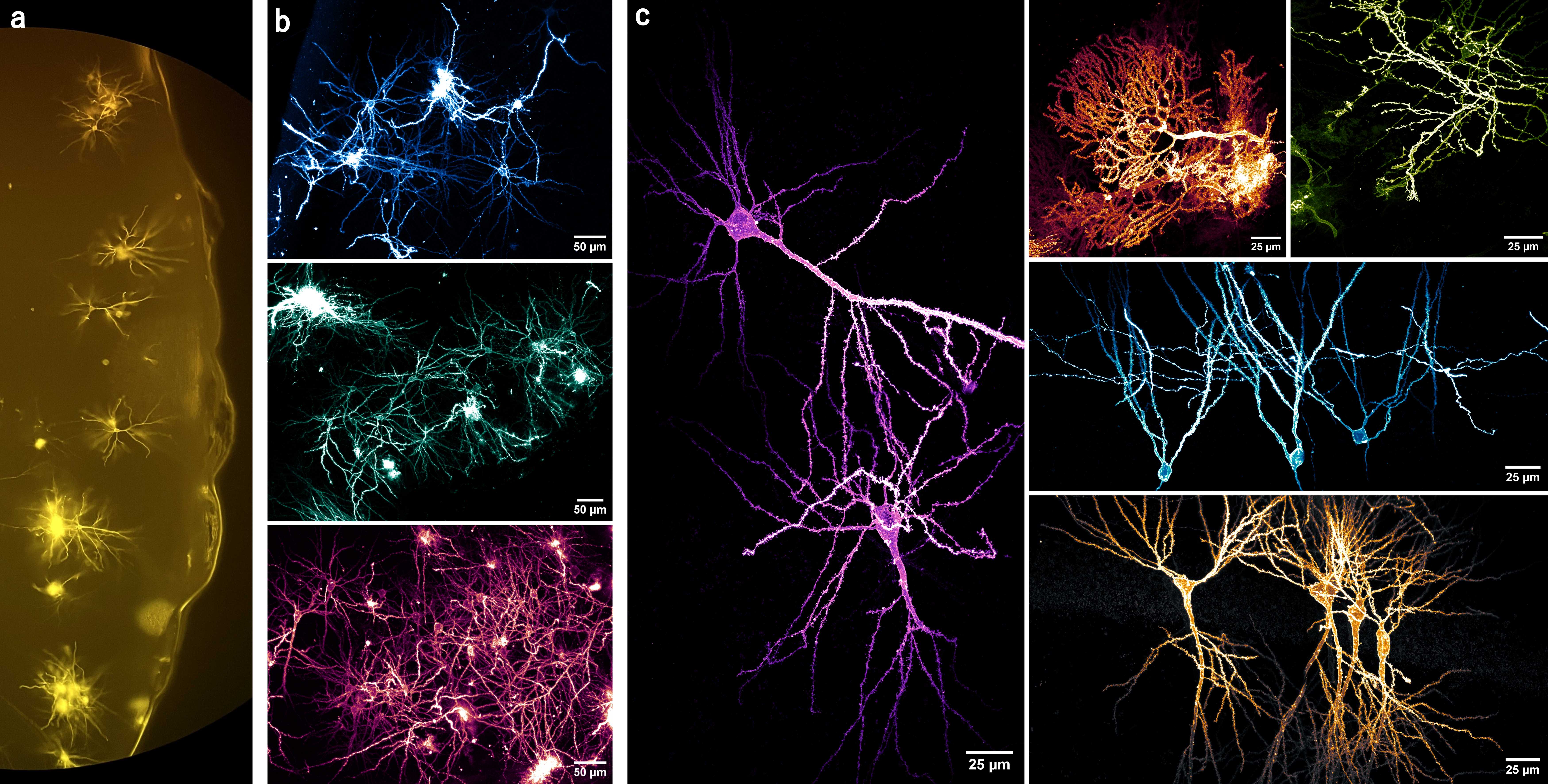
- Figures 9a & 9b illustrate the variation in the neuronal labelling patterns and sizes of the DiI crystals/spots produced by this method. Overall, a large population of neurons are randomly labelled.
- This method's labelling pattern allows the neuronal morphology to be clearly observed, as depicted by the diverse types in figure 9c . Moreover, the order and origin of the dendritic branches can be easily traced back to the soma, making it suitable for dendritic analyses (see figure 10 ).
- Of course, not every dye spot on the tissue results in neuronal labelling, perhaps due to DiI clumping, failure to incorporate into the tissue, tissue damage, or landing in the neuropil, etc. And not every labelled neuron will be suitable for sampling due to truncation (see figure 10d ), insufficient labelling, perpendicular projections or projections beyond the working distance, being obscured by other features &/or cells, etc.
- The sampling criteria will differ depending on the features and analyses of interest. For example, dendritic spine imaging is rather complex and warrants further considerations that are beyond the scope of this protocol (see the literature listed in the guidelines for more information).
- Nevertheless, this method labels a large population of neurons, with plenty suitable for sampling. The following literature provides a good starting point for guidelines on sampling - Dickstein et al. (2016), Dumitriu et al. (2011), and Wu et al. (2004).


