Protocol for Facially Guided Digital Diagnosis in Orthodontics and Interdisciplinary Dentistry
Rupert HG Kelley, Álvaro Ferrando Cascales, Raúl Ferrando Cascales
Disclaimer
Informed consent was obtained by the authors from all people whose photos are shown in this publication permitting use of their photos without anonymisation.
Abstract
As the digital age of dentistry continues to flourish, it has never been more important to have protocols to guide dentists through the planning and performance of treatments using the latest technology and software. This is especially true in the field of orthodontics, where the use of technology has revolutionised treatment outcomes. During the first stages of this protocol, extensive records are collected which are then used throughout the treatment. These records are superimposed to provide a 3D 'virtual patient'. After that, a shift occurs from two dimensions to three dimensions, and movement of the maxillary teeth begins. Then, the mandibular teeth are moved, and the case is completed. The final step is to check the results and ensure that the outcome matches what was planned before the commencement of treatment. This protocol aims to guide orthodontists in the treatment of their patients no matter the type of treatment that is planned, whether orthodontic, restorative or surgical. At any stage of the treatment, the orthodontist can refer back to the protocol to stay on the path towards a successful outcome for the patient.
Steps
Treatment Planning
STEP 1 - Records: Natural head position pictures, occlusal scan and radiographic imaging
This first essential step forms the basis of the protocol and provides digital records that can be used in the subsequent steps. A full series of facial photographs are taken in the natural head position (NHP). The orthodontist uses their judgment to find this position, ensuring that the patient is relaxed and looking into the distance at a point at the same level as their eyes. A complete series of intraoral photographs is also captured.
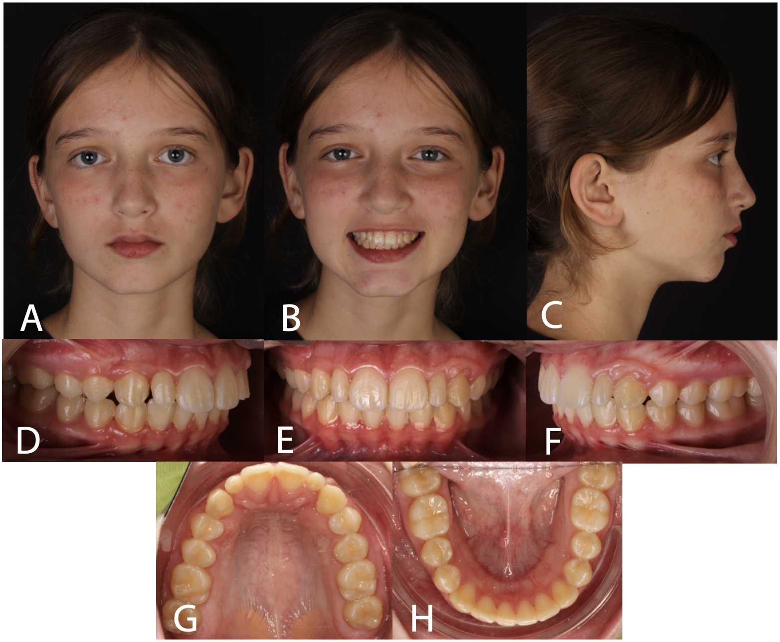
In addition to photographic records, digital intraoral scans are taken of the upper arch, lower arch, and of the patient’s occlusion, which will generate the STL files. In cases where the patient has a stable bite, the occlusal scan will be taken with the patient in maximum intercuspation. If the patient presents an unstable bite, then a stable orthopaedic position can be found and recorded using a wax registration. This position can then be recorded using the intraoral scanner. CBCT imaging can provide vast amounts of information, however, it is up to the clinician to decide when they feel this is necessary. In the subsequent steps of the protocol, CBCT provides information that facilitates the superimposition of the facial photographs with the digital scans, to mount the virtual articulator, to segment the roots of the teeth and to assess the midface and lower face as part of a comprehensive digital diagnosis.
NHP photographs and intraoral scans are considered mandatory for this protocol. A CBCT may be chosen by the clinician on a case-by-case basis. If a CBCT is not carried out, then panoramic or lateral cephalometric X-rays can be performed instead.
STEP 2 - Orientation and alignment of STL and DICOM files with photographs
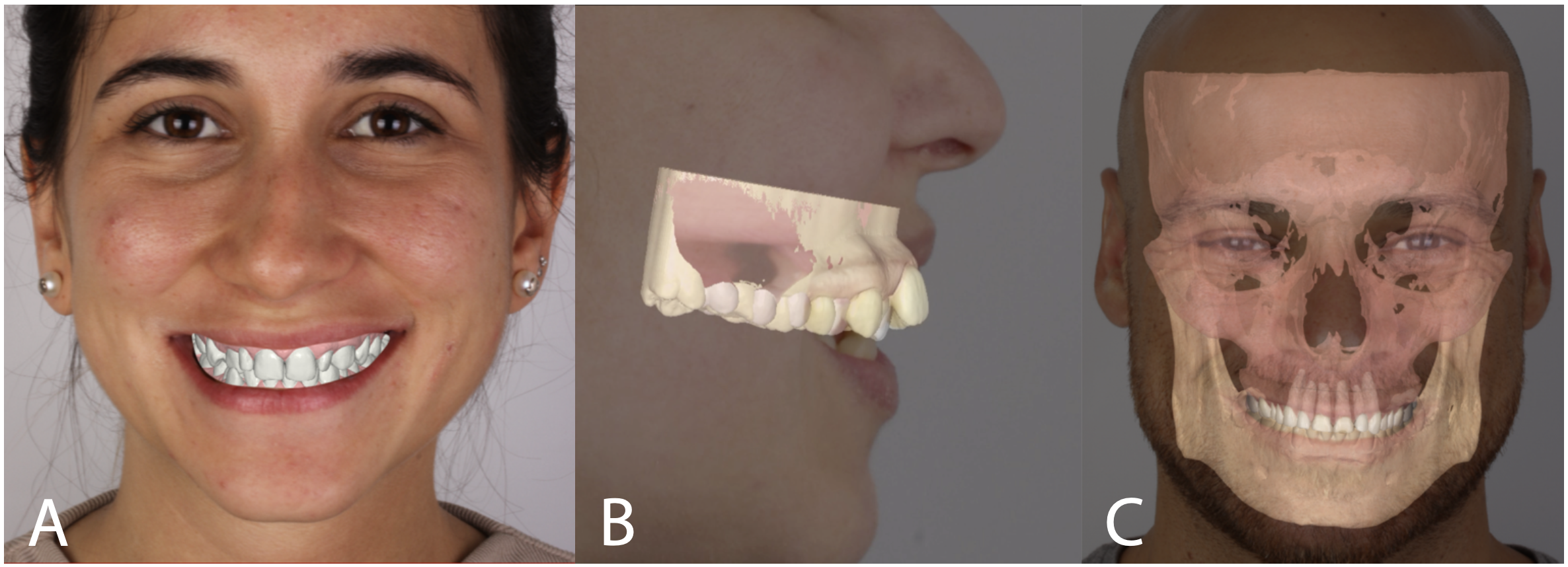
Once all the records have been obtained, the digital scans (STLs) can be superimposed onto the NHP photographs using a software package such as NemoCeph (Nemotec SL, Madrid, Spain). If a CBCT was taken, then the DICOM file can also be superimposed onto the photographs using the same software. Landmarks imaged in the CBCT aid in the superimposition process. The key in this stage is to obtain the precise orientation of the STL and DICOM files based on the natural head position. Correct orientation of the digital records facilitates accurate determination of desired movements. Modern orthodontic software packages use artificial intelligence (AI) to perform this superimposition procedure.
STEP 3 - Occlusal analysis: Crowding and virtual articulator
Analysis of any crowding or diastemas in the upper and lower arches forms part of the next step of the protocol. The presence or absence of these factors in the upper arch guides the first stages of the treatment. Based on these measurements, it may be determined that treatments such as extractions or skeletal or dentoalveolar expansion are required. In some cases, the magnitude of the sagittal and vertical facial imbalances necessitates the consideration of orthognathic surgery to reach reasonable and stable overall treatment goals.
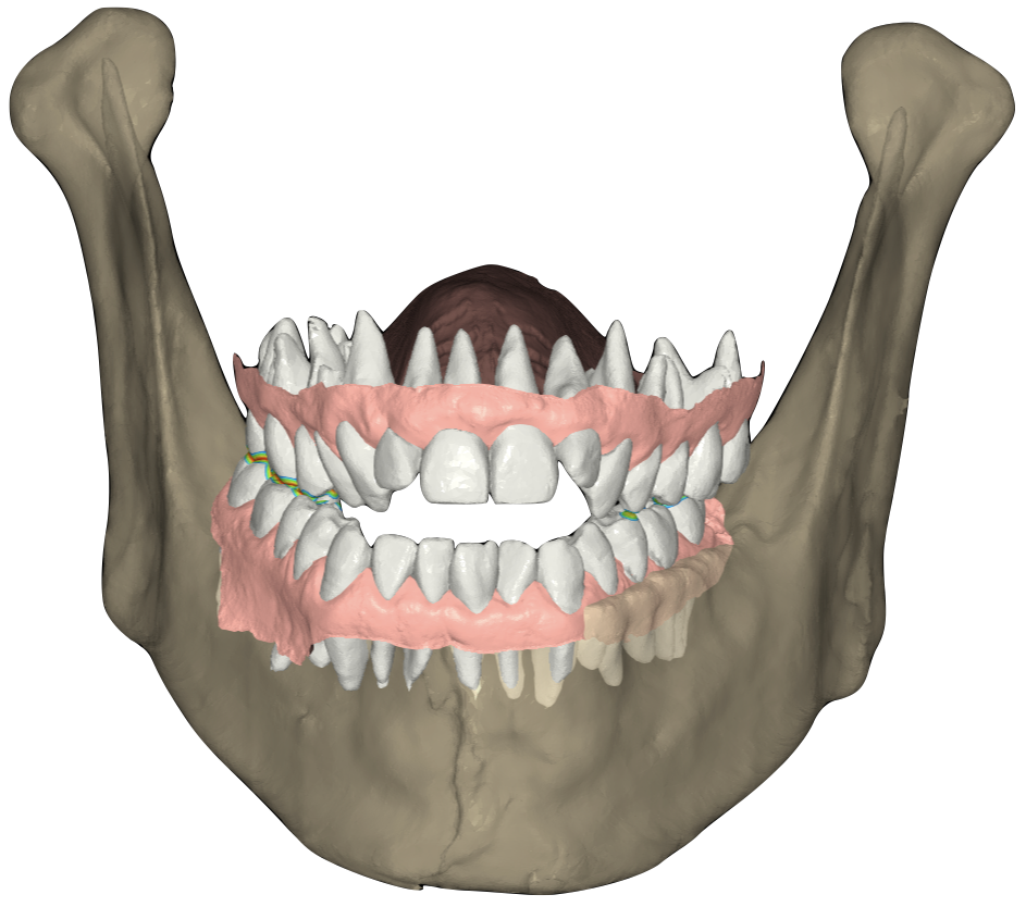
Next, we can observe the occlusal relationship using the virtual articulator. This includes the initial contact in centric relationship, interferences, and the occlusal contacts present during protrusive and lateral movements. The virtual articulator is constructed based on imaging of the condyles, glenoid fossa and cranial base provided by the CBCT and all three parts of the intraoral scan (upper arch, lower arch, and interocclusal). Furthermore, the curves of Wilson and Spee can be measured to determine whether flattening of the curves is required and the space required to do this.
STEP 4 - 2D cephalometric analysis and 2D VTO/STO
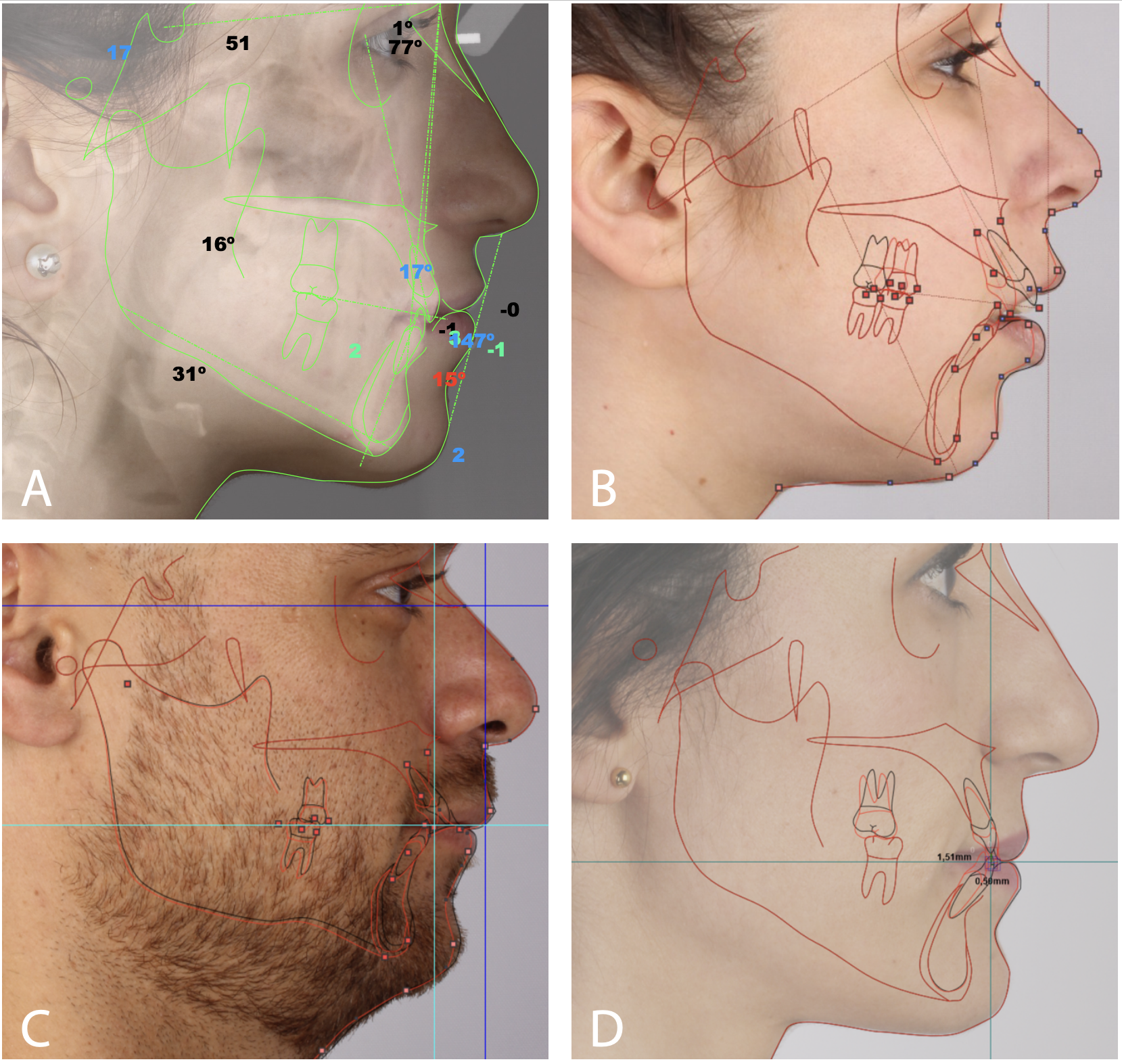
A 2D cephalometric analysis is carried out to determine the patient's current situation and to establish the measurements outside of the normal ranges. First, an analysis of the hard tissues is performed to determine the patient's facial pattern and their skeletal class. A cephalometric analysis is then required (i.e., Ricketts, Steiner, Jarabak or McNamara analysis). Following this, a further analysis is performed to provide information on the soft tissue structures and their projection to the true vertical line. An Arnett analysis is suggested, or the Ayala method if surgery is planned. The key in this step of the protocol is to firstly determine the desired position of the maxillary central incisors from a 2D sagittal view (following Arnett’s method), before transferring this position to 3D in the next step of the protocol. This forms an important part of the treatment planning as these are the teeth that will be virtually moved first. Their vertical position regarding the upper lip is a crucial measurement. Arnett described that there should be 3.9mm of maxillary incisor exposure at rest in males and 4.7mm in females. According to Arnett, it is also acceptable to show 2mm of gingival tissue above the maxillary anterior teeth when smiling.
After the cephalometric analysis, a VTO is performed with attention to crowding and cephalometric discrepancy. The desired projection of the maxillary central incisor and the interincisal angle can be visualised. In case surgical correction is considered necessary to achieve the amount of dental movement required, an STO can be performed, once again following Ayala’s method.
Movement of Teeth
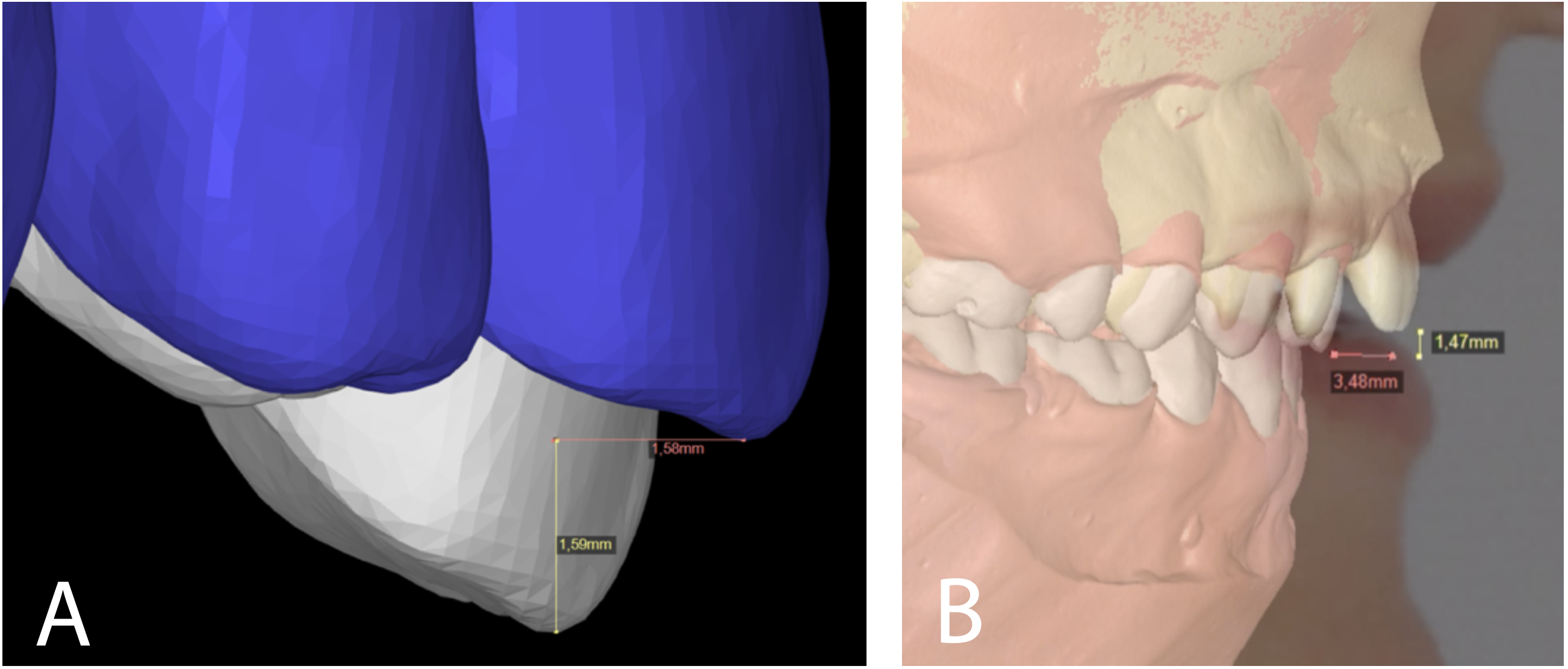
STEP 5 - Transfer sagittal values from VTO/STO to SETUP based on NHP pictures
In the previous step, the projection of the maxillary central incisor was determined in a 2D sagittal view. Now, this position in VTO/STO (2D) is transferred to SETUP (3D) using the most incisal point of this tooth. At this stage, work continues to take place from the lateral view of the patient. Therefore, the anteroposterior and vertical position of the central incisors are the critical measurements. Now, the virtual movement of the maxillary central incisors can begin, followed by the other maxillary teeth in the sequence:
Central incisors -> Lateral incisors -> Canines -> Premolars -> Molars
The maxillary central incisor that is in the most unfavourable position is selected to be moved first, followed by the contralateral central incisor. Planning the movements of the upper arch in this sequence enables the orthodontist to achieve a harmonic arch shape. Once the correct anteroposterior and vertical position of the maxillary teeth has been achieved, rotations can be planned.
STEP 6 - Frontal analysis with STL and NHP pictures
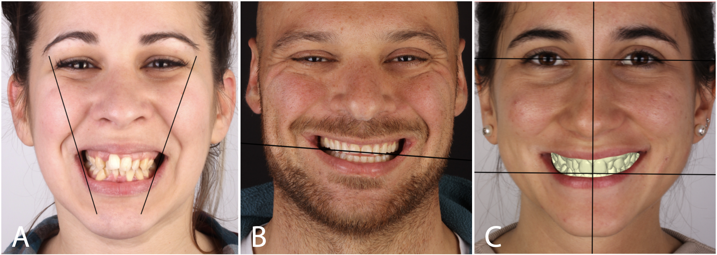
At the start of this step, attention shifts from the lateral view of the patient to the frontal view, whereby a frontal facial analysis is performed. This step has three keys: transverse dimension of the maxilla, transverse angulation of the occlusal plane (canting), and symmetry of the midlines.
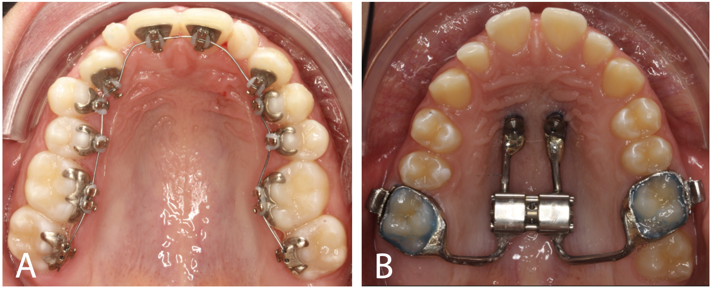
First, the midline is corrected, then canting, and finally, the transverse dimension of the maxilla. During this stage, techniques including maxillary expansion (either tooth or bone-anchored SARPE), temporary anchorage devices (TADs), etc., may be used to achieve a desired transversal result for the maxilla and upper dentition. Before moving to the next stage, it should also be checked that the arch contour is parallel to the smile line.
STEP 7 - Establish precise teeth movements (SETUP)
Now that the future position of the upper dentition has been chosen, the focus of the orthodontist moves to the lower arch. Once again, planning moves in a distal direction from tooth to tooth. The mandibular central incisors are placed in a correct overbite and overjet with the maxillary central incisors. Then, the rest of the mandibular teeth are virtually moved in the sequence:
Central incisors -> Lateral incisors -> Canines -> Premolars -> Molars
Just like with the upper arch, once the correct anteroposterior positions have been planned, the virtual position of each tooth is corrected to give the desired arch shape. At the end of this stage of the protocol, a functional occlusion should have been established. A Bolton analysis is performed to determine that there is a correct mesiodistal tooth size relationship between the maxillary and mandibular teeth. If this relationship is incorrect, alterations such as interproximal reduction or composite build-ups can be planned.
STEP 8 - Decision on mechanics and/or technique to be used
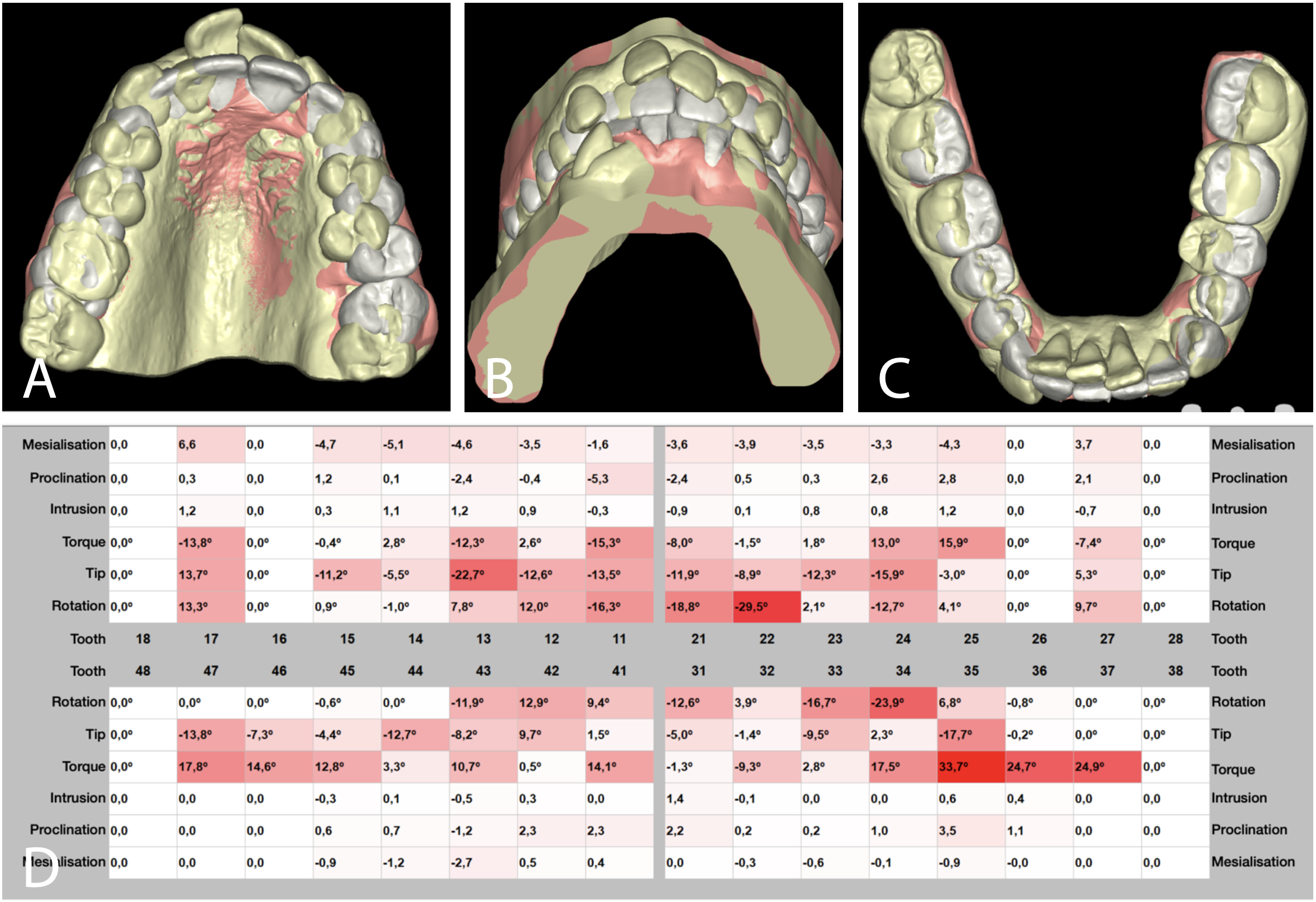
Now that the virtual movement of the upper and lower teeth has been completed, the position of each tooth can be analysed and compared to the initial positions. Based on the results of this analysis, tooth movement complexity becomes clear to reach the overall objectives. The choice of mechanics or technique is guided by the expertise and experience of the orthodontist and by the magnitude of the required movement. For example, if a molar intrusion of 1mm is required, this can be performed orthodontically, but if 3mm of intrusion is required, skeletal anchorage would be required. It may also be found during this stage that the relationship between the arches does not meet the objectives. In this situation, further techniques such as expansion or Class II/III intermaxillary teeth movements may be required.
Verification of Results
STEP 9 - Verification of results - 3D superimposition
During this final step, an analysis of the results is performed. If the objectives have been met, then the treatment has been successful. If not, then the reasons for the failure should be found, and further management needs to be considered and carried out as described in the previous step of the protocol.
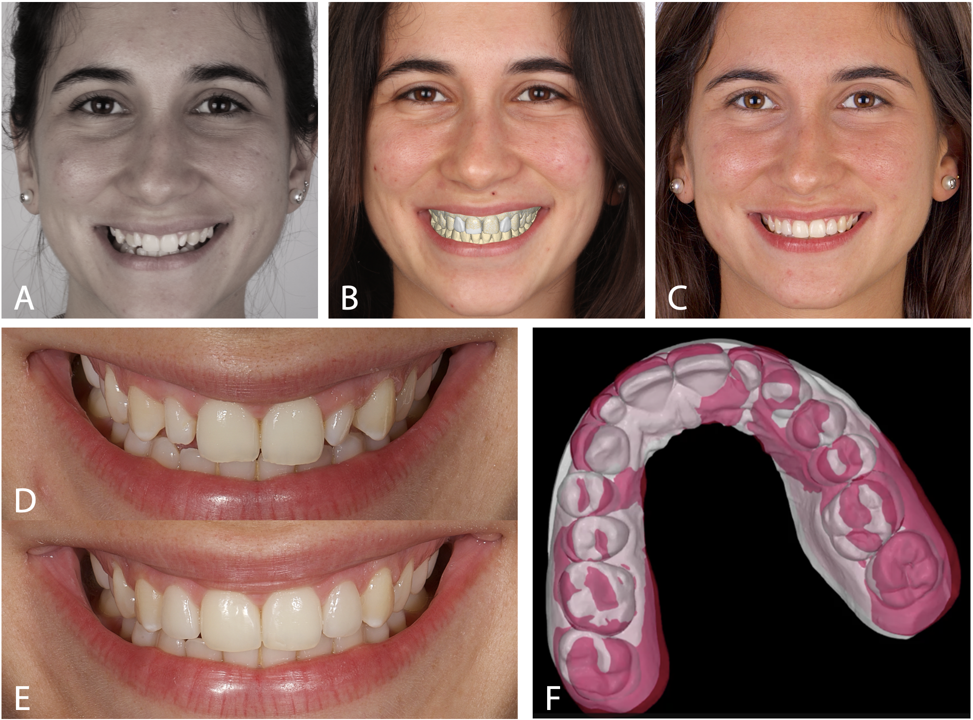
2D superimpositions such as pre-and post-treatment cephalometric analyses can provide useful information regarding the success of the treatment, but not exact quantitative values. To quantify the results and provide exact numerical discrepancies, a 3D superimposition can be performed using a pre-treatment and post-treatment STL file using a stable anatomical reference. If available, DICOM files can also be superimposed to verify treatment results. The superimposition of STL files is useful for tracking the results of dental movement. Superimposition of DICOM files has value in tracking growth and the result of surgical treatment, whereby the cranial base can be aligned and certain points such as the anterior nasal spine can tracked.
Finally, it must be mentioned that photography and videography are very powerful tools that allow orthodontists to verify the results of their treatment. Given that this protocol is facially guided, the final result must be aesthetically acceptable in the face of the patient. Videos of the patient talking and smiling can be taken to provide valuable information on conversational aesthetics, which may not be provided by traditional static imaging.
