3D Mesh Cleanup Tutorial: Sphenodon (Intermediate)
Elizabeth G. Clark, Kelsey M Jenkins, Craig R Brodersen
Abstract
This protocol details 3D mesh cleanup tutorial of sphenodon (intermediate).
Attachments
Steps
Part 1: Making and sculpting simple shapes in Autodesk Maya 2020
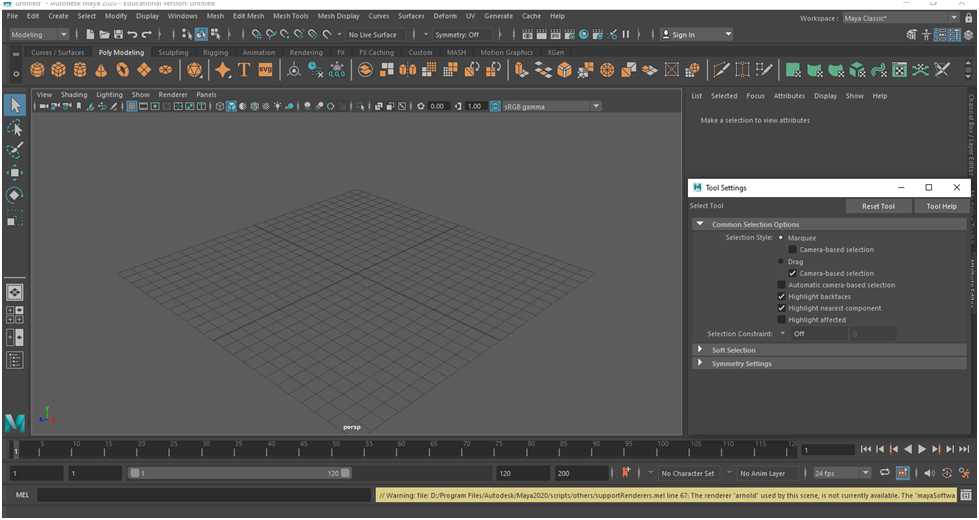
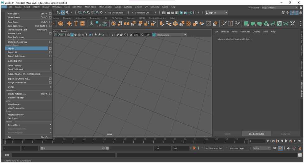
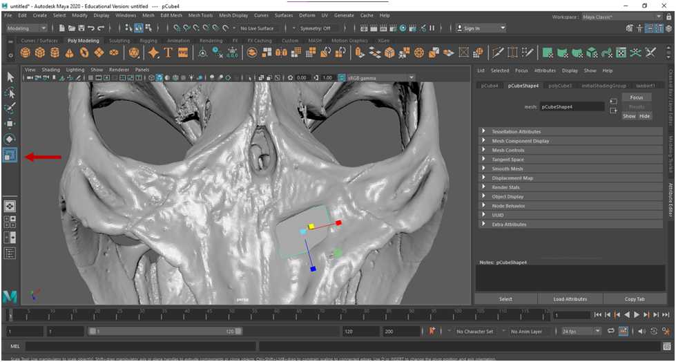
Open Maya . A new scene in Maya will appear similarly to the image below.
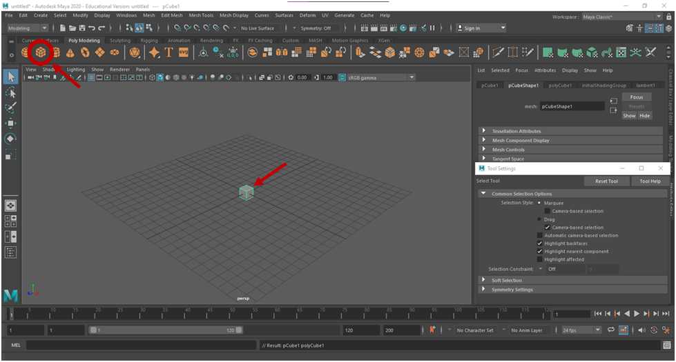
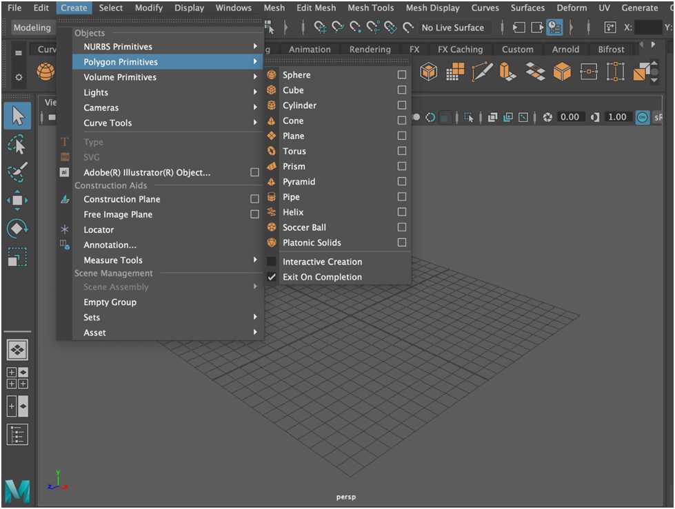
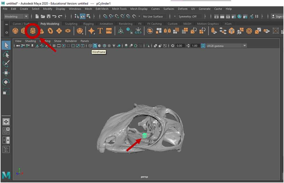
To begin making a simple shape, select the cube from the “Poly Modeling”” tab . When you click on the cube icon, a cube will appear in the center of the scene.
You can also create a polygon by going to Create > Polygon Primitive and selecting the cube.
To zoom in on the scene, scroll using the center scrolling button on the mouse or Alt + Right Mouse Button . You can move around the scene using Alt + Left Mouse Button (tumbling, or circular movement around the scene) and Alt + Center Scrolling Mouse Button (maintains angle while panning view).
Integral to the sculping process are the translate, rotate, and scaling tools. Selecting any of these tools will toggle new icons to appear within the cube that will allow you to move, rotate, and resize the cube in the x, y, and z planes.
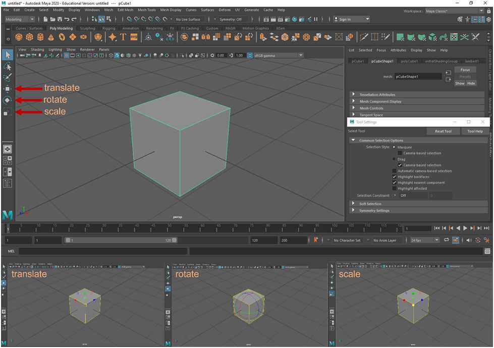
Take a few minutes to practice these tools and change the size, shape, and position of the cube to look like the image below.
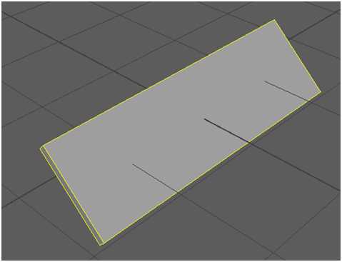
Once you have achieved this shape, you can delete it by selecting Delete or Backspace.
Now that you have interacted with the scaling tools, we will practice simple sculpting. Create a new cube again by selecting the cube from the “Poly Modeling” tab . Then, scale the cube so that it is thinner in one axis and equidistant in the other two axes, as in the image below.
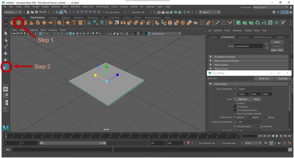
To make a simple shape, such as the cube, more malleable for digital sculpting, subdivisions can be added to the cube. With the cube selected, navigate to the polyCube tab of the Attribute Editor . Add subdivisions to the Width, Height, and Depth by changing the value of each to 10 .
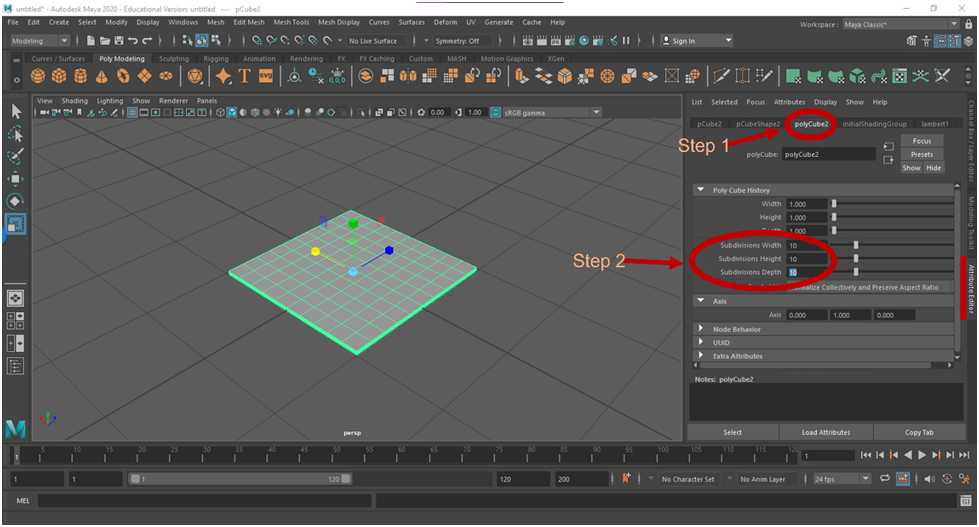
In order to manipulate the new faces created by these subdivisions, hold the right mouse button, and then select Edge from the new pop-up menu that appears .
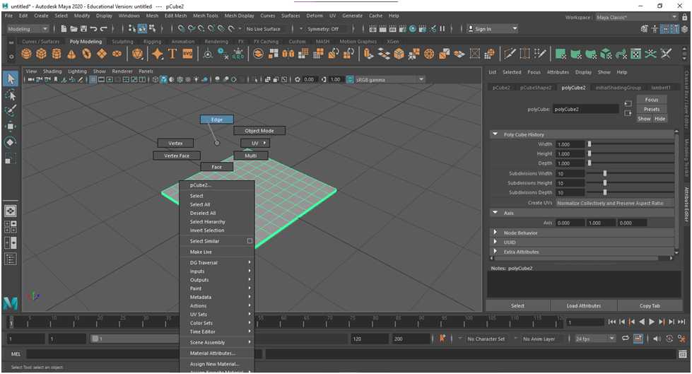
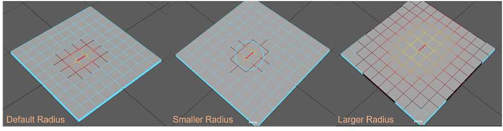
Now that you are in Edge Mode, hover over the cube . You will notice that a radius of edges is highlighted. As you sculpt objects in Maya, you may want to decrease or increase the size of the radius to affect fewer or more edges. To do this hold B + Left Mouse Button .
Now that you have played with these tools a bit, let us begin sculpting the cube mesh into a new shape.
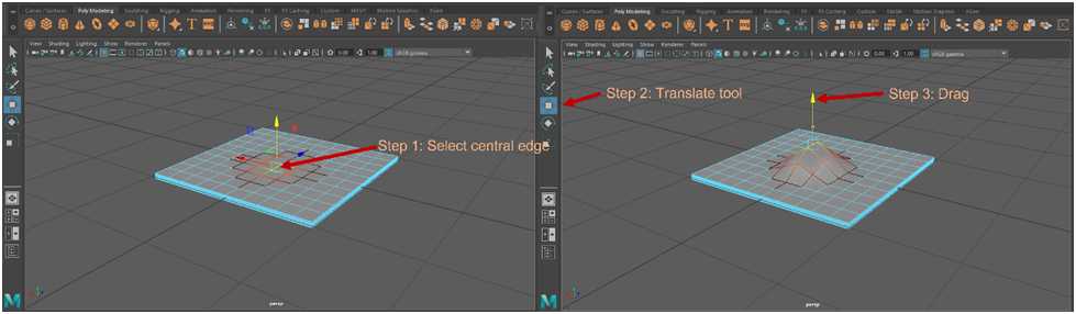
- Select an edge towards the center of the cube . To manipulate this edge and the affected radius, the translate, rotate, and scaling tools can be used.
- Select the translate tool, and then click and drag one of the axis arrows to see how it affects the mesh.
- To practice, try selecting different portions of the mesh and manipulate the mesh with the translate, rotate, and scaling tools.
- You can also select an entire row of edges by double clicking on a single edge within that row.
Part 2: Reconstruction using simple shapes (i.e., Simple-Patch Method)
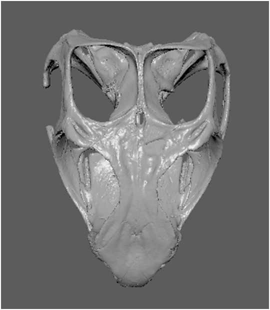
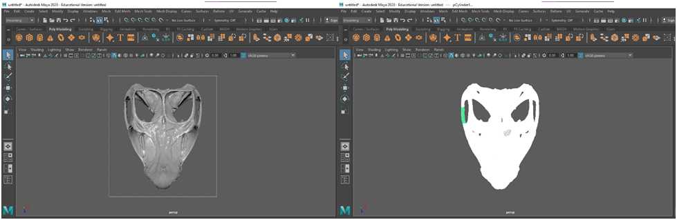
Import “Sphenodon with holes.stl” by selecting File > Import.
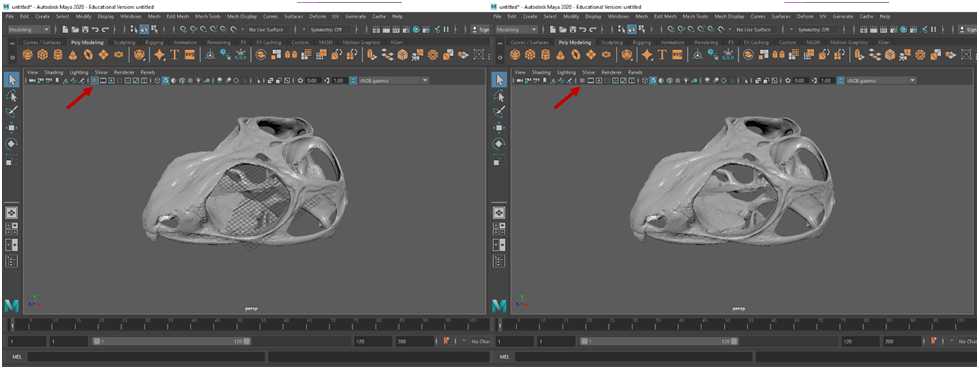
The mesh of the skull is somewhat larger than the reference grid in the Maya scene. If you find the grid cumbersome, the grid can be toggled on and off by selecting the grid icon .
Select the cube icon from the Poly Modeling tab .
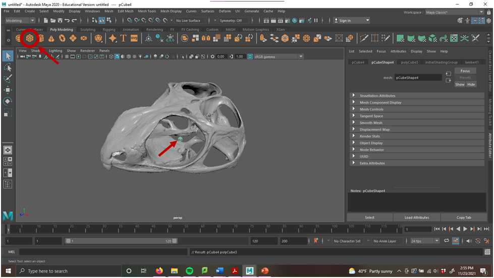
Using the translate tool, move the cube so that it centered within the hole being fixed. You may find it helpful to scroll around the scene to make sure the cube is aligned with the hole as closely as possible.
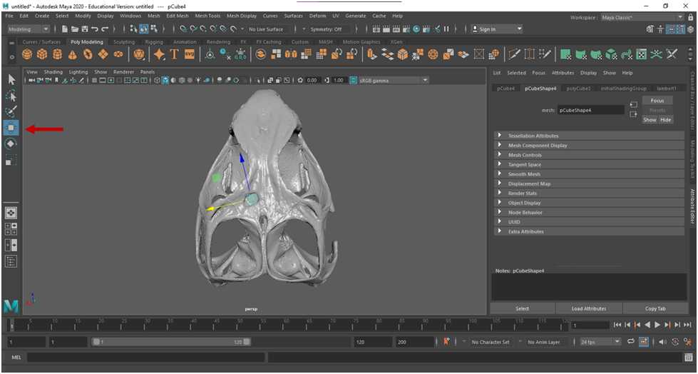
Using the scale tool, size the cube so that it approximately fits the size of the hole. You may also find it useful to fine-tune the placement of the cube using the rotate and translate tools.
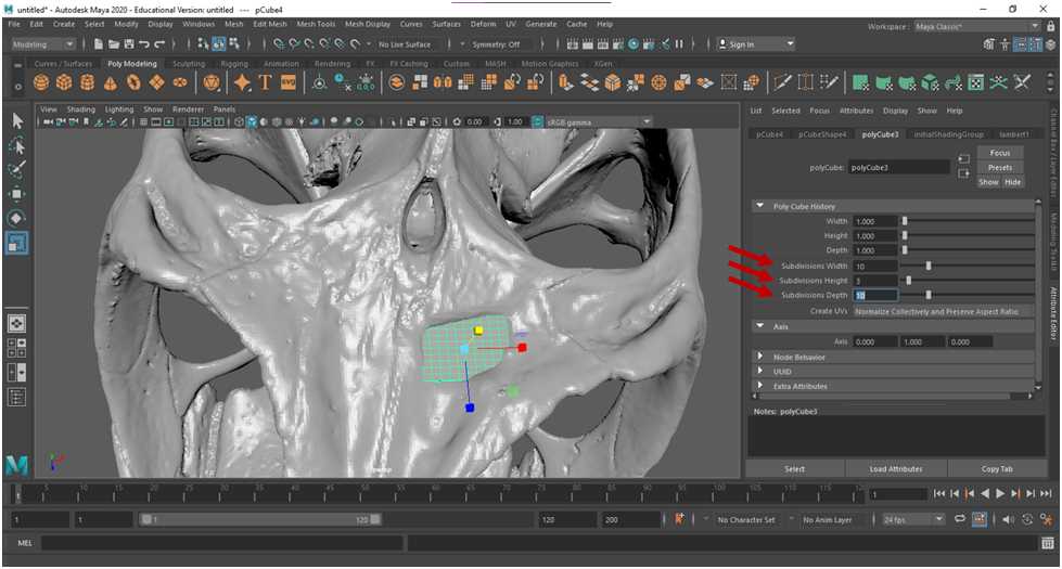
Add subdivisions to the cube byselecting the polycube tab from the Attribute editor . It is recommended to have more subdivisions for larger areas, and fewer subdivisions in smaller areas. In this example, there are 10 subdivisions for width, 3 for height, and 10 for depth.
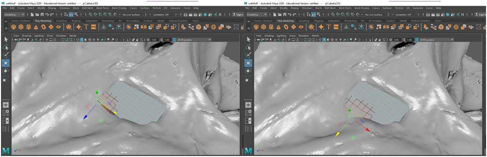
Now, switch to edge mode by holding the right mouse button > Edge . Now, the cube can be manipulated by its edges to match its surroundings using the scale, rotate, and translate tools as outlined in part one.
First, bury the edges of the patch within the original mesh . In example below, this was done by translating edges of the patch and dragging them within the borders of the skull.
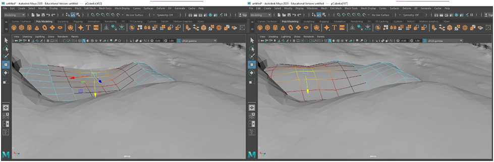
Second, use the translate tool so that sunken areas are flushed with the original model . This can be done by raising and lowering areas of the mesh to align with the morphology of the original model.
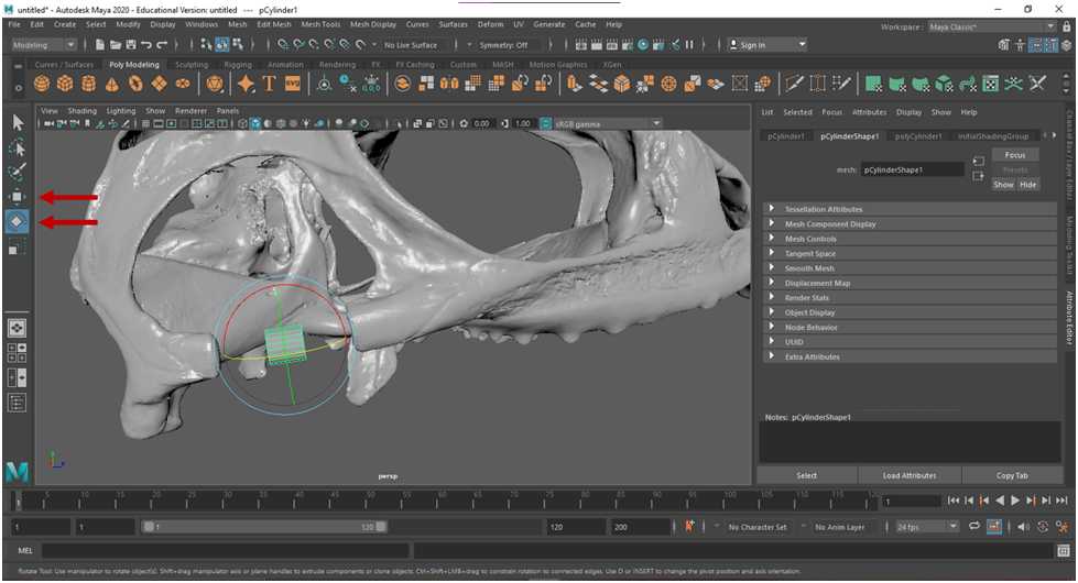
Next, repair the missing postorbital bar. This time, select the cylinder from the Poly Modeling tab .
Using the translate and rotate tools, align the cylinder with the post orbital bar.
Lengthen the cylinder in the direction of the post orbital bar using the scale tool.
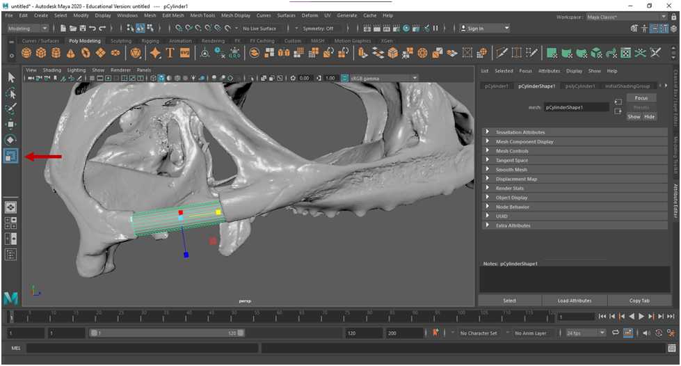
Resize the bar in the dorsal and lateral directions using the scale tool so to match the size and shape of the adjacent mesh. You may find it useful to toggle between the scale and rotate tools as you fit the new mesh to the skull mesh.
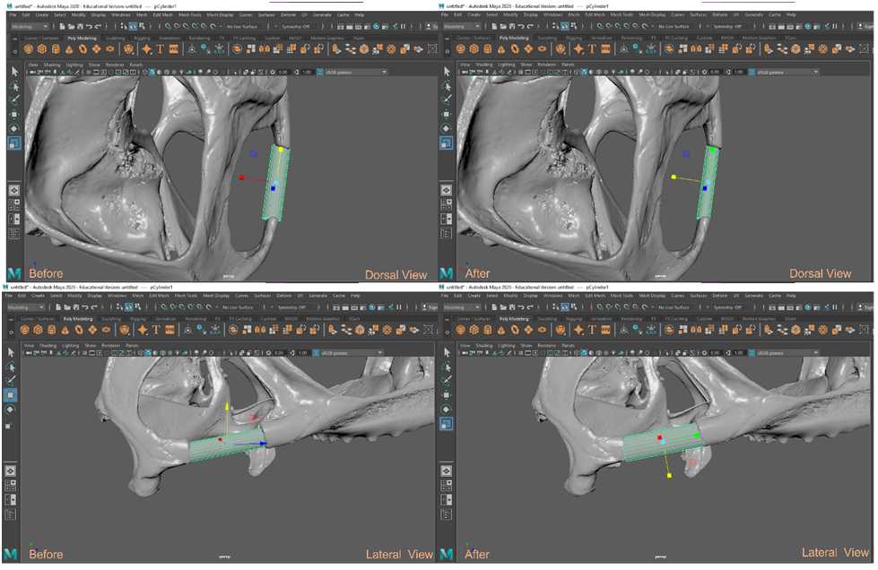
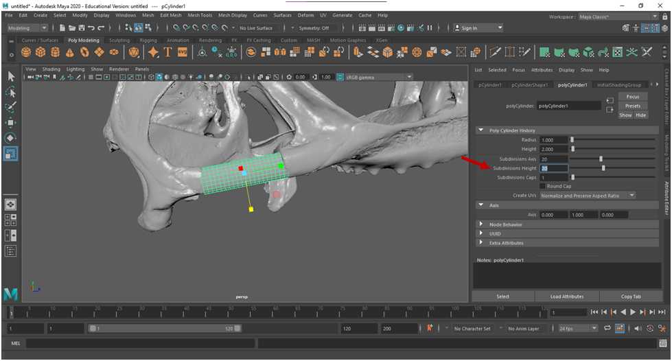
Once the cylinder is roughly sized, add subdivisions by selecting the polyCylinder tab of the attribute editor. You may notice that the “subdivisions axis” is already set to 20 subdivisions. Add 20 subdivisions to the height for fine tuning the mesh.
Similar to the simple patch method, switch to edge mode by holding the right mouse button and selecting Edge. Just like the patch, the cylinder edges should be buried within the skull mesh to hide rough edges .
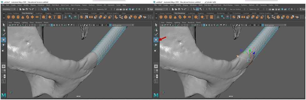
Fine tune the mesh by manipulating it until the desired shape is achieved, in this case it should look similarly to the post orbital bar on the opposite side of the model.

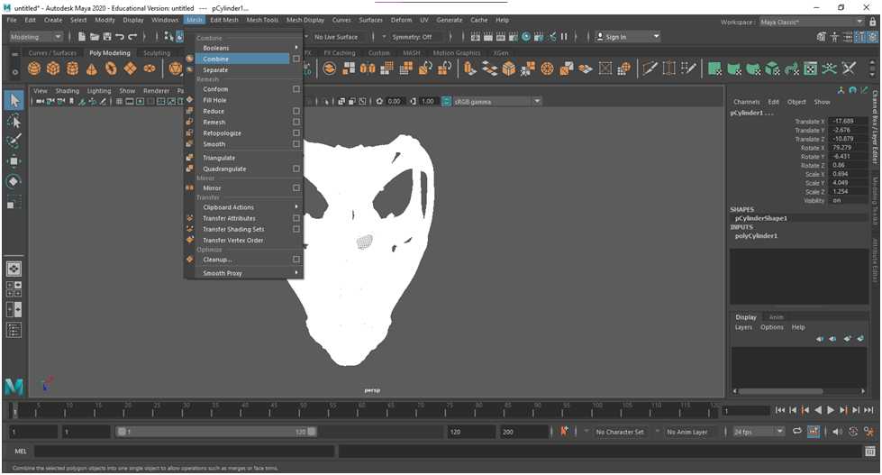
To combine the new meshes with the original model, enter object mode by holding the right mouse button and selecting the “Object Mode” icon. Then select the selection tool icon.
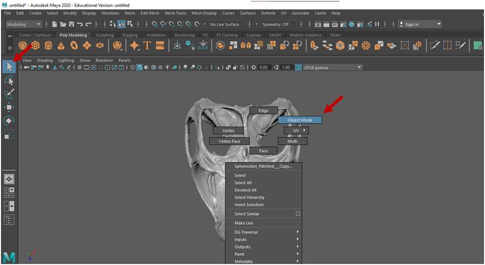
Select all components (the original model and two patches) by dragging the cursor around all the meshes , creating a box around all the elements in the scene.
Combine the selection by going to Mesh > Combine .
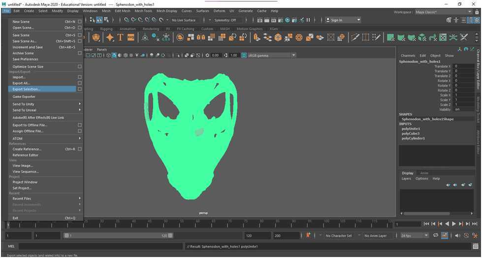
Export mesh by going to File > Export Selection. In the new pop-up window, name the file “Sphenodon Patched” and export selection as an .stl or .obj.

Shrinkwrapping and File Reduction
While the mesh is now patched, the model is still technically multiple meshes (the skull and two patches) instead of a single unified mesh. You may choose to keep the model in this format, though having multiple mesh elements may complicate downstream analyses. To rectify this, a shrinkwrap can be applied.
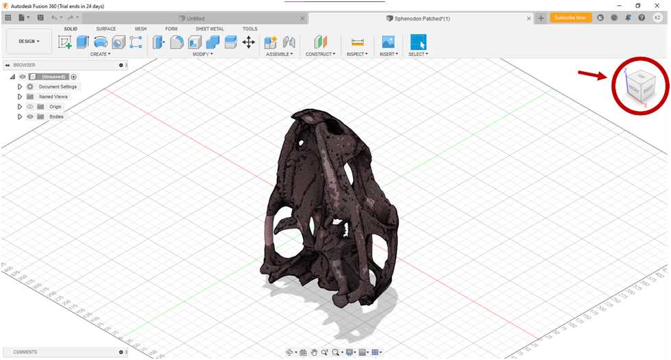
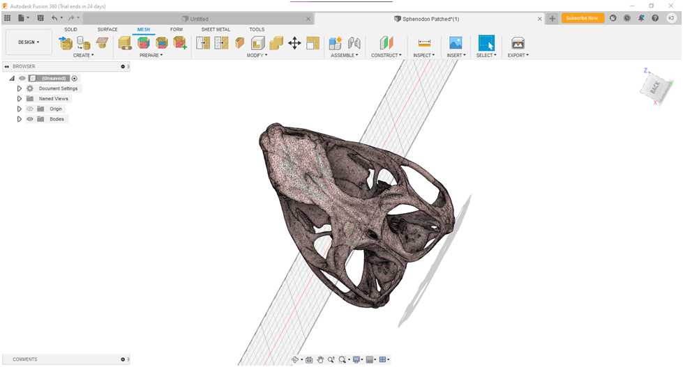
Open Autodesk Fusion 360. Open the file by selecting the File Icon > Open… > Open from my computer…
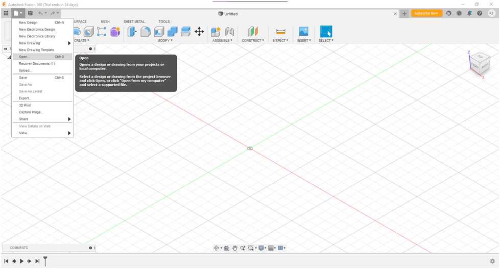
Once the model loads, the view can be rotated by toggling the view cube in the top right corner.
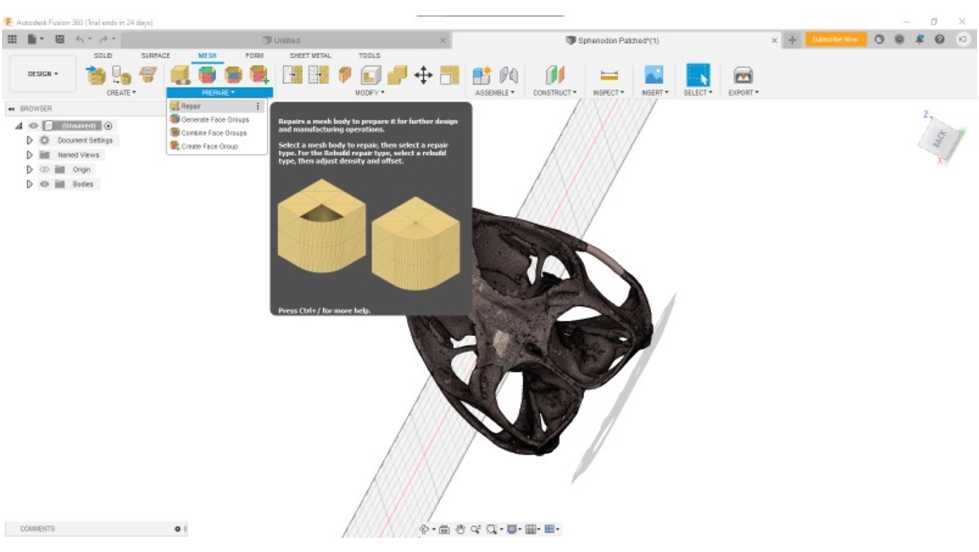
To begin, select the Mesh tab. Under that tab, select Prepare > Repair . A pop-up window will appear.
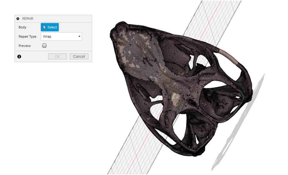
In the pop-up window click Select and then select the model in the scene. Repair type should be changed to Wrap. You may opt to view a Preivew by selecting the preview tab, but note that this task may take several minutes depending on the number of faces in the model. Click OK to create the shrinkwrap.
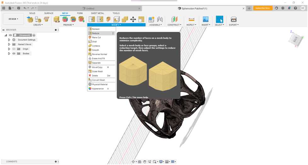
Once the shrink wrapping is complete, the mesh can be exported. However, you may want to consider also minimizing the number of faces in the mesh to further simplify the model to reduce the total file size. Be aware that this will also reduce some of finer details in the model. To do this, select Mesh > Modify > Reduce . A pop-up dialog box will appear.
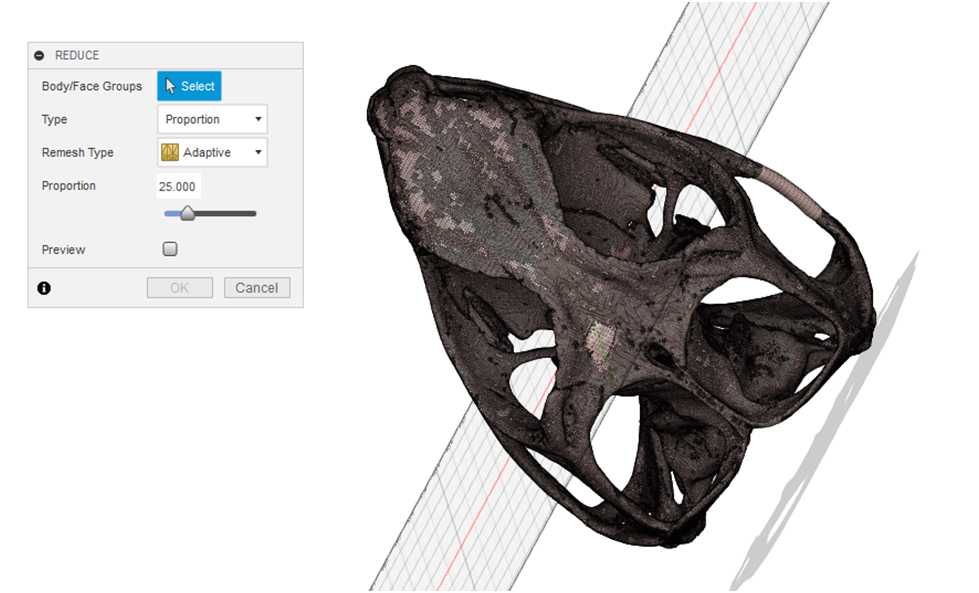
Click select and select the model in the scene by dragging a box around the model. There are several ways to reduce the face count, either by proportion or by face number. In this example, the number of faces are reduced by a proportion of 25, in that the original number of faces are reduced to 25% of the original value. Remesh type is Adaptive. Again, you may opt to view a preview. Select OK.
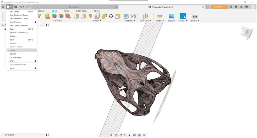
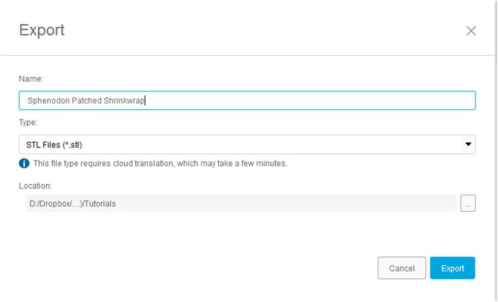
To export the model, select the File Icon > Export.